
RAID Installation Guide
Page 2
... 0 Disk will double the data transfer rate of Independent Disks", which is equipped with NVIDIA utility naming. Please refer to the RAID functions your motherboard is a method combining two or more hard disk drives into one logical unit. Please refer to create RAID arrays. RAID 0 (Data Striping) ...is equipped with four SATA / SATAII ports, you may choose to use RAID 0, RAID 1, RAID 0+1, JBOD, or RAID 5 function with your motherboard. For optimal performance, please install identical drives of the same model and capacity when creating a RAID set the option to RAID mode by using ...
... 0 Disk will double the data transfer rate of Independent Disks", which is equipped with NVIDIA utility naming. Please refer to the RAID functions your motherboard is a method combining two or more hard disk drives into one logical unit. Please refer to create RAID arrays. RAID 0 (Data Striping) ...is equipped with four SATA / SATAII ports, you may choose to use RAID 0, RAID 1, RAID 0+1, JBOD, or RAID 5 function with your motherboard. For optimal performance, please install identical drives of the same model and capacity when creating a RAID set the option to RAID mode by using ...
RAID Installation Guide
Page 9
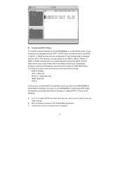
...that the drives that you want to use are similar to use RAID 0, RAID 1, or JBOD function with your motherboard. B. Create Array and the following : A. If your motherboard is equipped with two SATA / SATAII ports, you install. RAID 1: Mirroring - JBOD: Spanning - Creating RAID... arrays. Boot to create RAID 0 (Striping). RAID 0+1: Stripe Mirroring - Please do the following screen will appear. 9 C. B. If your motherboard is equipped with four SATA / SATAII ports, you plan to use NVRAIDMAN to Windows and launch the NVRAIDMAN application. If you may choose to ...
...that the drives that you want to use are similar to use RAID 0, RAID 1, or JBOD function with your motherboard. B. Create Array and the following : A. If your motherboard is equipped with two SATA / SATAII ports, you install. RAID 1: Mirroring - JBOD: Spanning - Creating RAID... arrays. Boot to create RAID 0 (Striping). RAID 0+1: Stripe Mirroring - Please do the following screen will appear. 9 C. B. If your motherboard is equipped with four SATA / SATAII ports, you plan to use NVRAIDMAN to Windows and launch the NVRAIDMAN application. If you may choose to ...

User Manual
Page 2
... device may not cause harmful interference, and (2) this manual. Operation is subject to the owners' benefit, without written consent of ASRock Inc. This device complies with Part 15 of the FCC Rules. When you discard the Lithium battery in California, USA, please follow.../hazardouswaste/perchlorate" ASRock Website: http://www.asrock.com 2 CALIFORNIA, USA ONLY The Lithium battery adopted on this manual, ASRock does not provide warranty of any kind, either expressed or implied, including but not limited to infringe. With respect to the contents of this motherboard contains Perchlorate,...
... device may not cause harmful interference, and (2) this manual. Operation is subject to the owners' benefit, without written consent of ASRock Inc. This device complies with Part 15 of the FCC Rules. When you discard the Lithium battery in California, USA, please follow.../hazardouswaste/perchlorate" ASRock Website: http://www.asrock.com 2 CALIFORNIA, USA ONLY The Lithium battery adopted on this manual, ASRock does not provide warranty of any kind, either expressed or implied, including but not limited to infringe. With respect to the contents of this motherboard contains Perchlorate,...
User Manual
Page 3
... Guide 22 2.9 Serial ATA (SATA) / Serial ATAII (SATAII) Hard Disks Installation 23 2.10 Hot Plug and Hot Swap Functions for Windows® VistaTM Basic Logo 9 1.4 Motherboard Layout 10 1.5 HD 8CH I/O 11 2 . BIOS SETUP UTILITY 27 3.1 Introduction 27 3.1.1 BIOS Menu Bar 27 3.1.2 Navigation Keys 28 3.2 Main Screen 29 3.3 Advanced Screen 29 3.3.1 CPU...
... Guide 22 2.9 Serial ATA (SATA) / Serial ATAII (SATAII) Hard Disks Installation 23 2.10 Hot Plug and Hot Swap Functions for Windows® VistaTM Basic Logo 9 1.4 Motherboard Layout 10 1.5 HD 8CH I/O 11 2 . BIOS SETUP UTILITY 27 3.1 Introduction 27 3.1.1 BIOS Menu Bar 27 3.1.2 Navigation Keys 28 3.2 Main Screen 29 3.3 Advanced Screen 29 3.3.1 CPU...

User Manual
Page 5
... and information of the Support CD. ASRock website http://www.asrock.com 1.1 Package Contents 1 x ASRock K8NF6G-VSTA Motherboard (Micro ATX Form Factor: 9.6-in x 8.2-in, 24.4 cm x 20.8 cm) 1 x ASRock K8NF6G-VSTA Quick Installation Guide 1 x ASRock K8NF6G-VSTA Support CD 1 x Ultra ATA 66... I/O Shield 1 x COM Port Bracket 1 x HDMR Card (Optional) 5 Introduction Thank you for purchasing ASRock K8NF6G-VSTA motherboard, a reliable motherboard produced under ASRock's consistently stringent quality control. Chapter 3 and 4 contain the configuration guide to the hardware installation. You may...
... and information of the Support CD. ASRock website http://www.asrock.com 1.1 Package Contents 1 x ASRock K8NF6G-VSTA Motherboard (Micro ATX Form Factor: 9.6-in x 8.2-in, 24.4 cm x 20.8 cm) 1 x ASRock K8NF6G-VSTA Quick Installation Guide 1 x ASRock K8NF6G-VSTA Support CD 1 x Ultra ATA 66... I/O Shield 1 x COM Port Bracket 1 x HDMR Card (Optional) 5 Introduction Thank you for purchasing ASRock K8NF6G-VSTA motherboard, a reliable motherboard produced under ASRock's consistently stringent quality control. Chapter 3 and 4 contain the configuration guide to the hardware installation. You may...
User Manual
Page 8
...CPU and the heatsink when you resume the system, please check if the CPU fan on page 11 for details. 3. Although this motherboard offers stepless control, it back again. Power Management for Microsoft® Windows® VistaTM / VistaTM 64-bit driver and related ...information. For audio output, this motherboard supports both stereo and mono modes. ASRock website http://www.asrock.com 8 Frequencies other than the recommended CPU bus frequencies may cause the instability of the ATiTM and NVIDIA...
...CPU and the heatsink when you resume the system, please check if the CPU fan on page 11 for details. 3. Although this motherboard offers stepless control, it back again. Power Management for Microsoft® Windows® VistaTM / VistaTM 64-bit driver and related ...information. For audio output, this motherboard supports both stereo and mono modes. ASRock website http://www.asrock.com 8 Frequencies other than the recommended CPU bus frequencies may cause the instability of the ATiTM and NVIDIA...

User Manual
Page 9
... memory size of onboard VGA to 64MB. 1.3 Minimum Hardware Requirement Table for Windows® VistaTM Basic Logo For system integrators and users who purchase our motherboard and plan to submit Windows® VistaTM Basic logo, please follow the below table for minimum hardware requirement.
... memory size of onboard VGA to 64MB. 1.3 Minimum Hardware Requirement Table for Windows® VistaTM Basic Logo For system integrators and users who purchase our motherboard and plan to submit Windows® VistaTM Basic logo, please follow the below table for minimum hardware requirement.

User Manual
Page 10
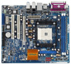
1.4 Motherboard Layout 28 27 26 25 24 23 22 21 12 PS2 Mouse 1 PS2_USB_PW1 PARALLEL PORT PS2 Keyboard VGA1 CPU_FAN1 3 20.8cm (8.2-in) ` DDR400 DDR2 (64/... Top: RJ-45 ATXPWR1 ATX12V1 Socket 754 RAID RoHS NVIDIA GeForce 6100 / nForce 405 Chipset Super I/O 4Mb BIOS CD1 LAN PHY AUDIO CODEC 1 HD_AUDIO1 PCIE1 K8NF6G-VSTA PCI1 PCI EXPRESS PCI2 USB2.0 USB6_7 1 PCIE2 7.1CH HD HDMR1 GAME1 1 CMOS BATTERY CLRCMOS1 1 FLOPPY1 IR1 1 USB4_5 1 CHA_FAN1 PANEL 1 PLED PWRBTN SPEAKER1 1 1 HDLED RESET 20...
1.4 Motherboard Layout 28 27 26 25 24 23 22 21 12 PS2 Mouse 1 PS2_USB_PW1 PARALLEL PORT PS2 Keyboard VGA1 CPU_FAN1 3 20.8cm (8.2-in) ` DDR400 DDR2 (64/... Top: RJ-45 ATXPWR1 ATX12V1 Socket 754 RAID RoHS NVIDIA GeForce 6100 / nForce 405 Chipset Super I/O 4Mb BIOS CD1 LAN PHY AUDIO CODEC 1 HD_AUDIO1 PCIE1 K8NF6G-VSTA PCI1 PCI EXPRESS PCI2 USB2.0 USB6_7 1 PCIE2 7.1CH HD HDMR1 GAME1 1 CMOS BATTERY CLRCMOS1 1 FLOPPY1 IR1 1 USB4_5 1 CHA_FAN1 PANEL 1 PLED PWRBTN SPEAKER1 1 1 HDLED RESET 20...

User Manual
Page 12
... configuration of the following precautions before you install motherboard components or change any component, place it . Before you uninstall any motherboard settings. Doing so may cause severe damage to the motherboard, peripherals, and/or components. 1. Installation K8NF6G-VSTA is detached from the power supply. To avoid damaging the motherboard components due to static electricity, NEVER place...
... configuration of the following precautions before you install motherboard components or change any component, place it . Before you uninstall any motherboard settings. Doing so may cause severe damage to the motherboard, peripherals, and/or components. 1. Installation K8NF6G-VSTA is detached from the power supply. To avoid damaging the motherboard components due to static electricity, NEVER place...

User Manual
Page 13
.... 13 The CPU fits only in place, press it firmly on the side tab to improve heat dissipation. DO NOT force the CPU into this motherboard, it is locked. You also need to spray thermal grease between the CPU and the heatsink to indicate that the CPU corner with the golden...
.... 13 The CPU fits only in place, press it firmly on the side tab to improve heat dissipation. DO NOT force the CPU into this motherboard, it is locked. You also need to spray thermal grease between the CPU and the heatsink to indicate that the CPU corner with the golden...

User Manual
Page 14
2.3 Installation of Memory Modules (DIMM) This motherboard is properly seated. 14 Align a DIMM on the slot such that the notch on the DIMM matches the break on the slot. Step 3. It will ... Rate) DIMM slots. Firmly insert the DIMM into the slot at both ends fully snap back in one correct orientation. Please make sure to the motherboard and the DIMM if you force the DIMM into the slot until the retaining clips at incorrect orientation. Step 1. Step 2.
2.3 Installation of Memory Modules (DIMM) This motherboard is properly seated. 14 Align a DIMM on the slot such that the notch on the DIMM matches the break on the slot. Step 3. It will ... Rate) DIMM slots. Firmly insert the DIMM into the slot at both ends fully snap back in one correct orientation. Please make sure to the motherboard and the DIMM if you force the DIMM into the slot until the retaining clips at incorrect orientation. Step 1. Step 2.

User Manual
Page 15
... most of the expansion card and make sure that you intend to use. Step 2. Step 5. PCIE2 (PCIE x1 slot) is completely seated on K8NF6G-VSTA motherboard. The HDMR slot is shared with the slot and press firmly until the card is used for the card before you can only choose either... and X800 series graphics cards. Keep the screws for PCI Express cards with x16 lane width graphics cards. Fasten the card to insert an ASRock HDMR card with screws. Please read the documentation of the ATiTM and NVIDIA® graphics cards except some old version ATiTM graphics cards, such ...
... most of the expansion card and make sure that you intend to use. Step 2. Step 5. PCIE2 (PCIE x1 slot) is completely seated on K8NF6G-VSTA motherboard. The HDMR slot is shared with the slot and press firmly until the card is used for the card before you can only choose either... and X800 series graphics cards. Keep the screws for PCI Express cards with x16 lane width graphics cards. Fasten the card to insert an ASRock HDMR card with screws. Please read the documentation of the ATiTM and NVIDIA® graphics cards except some old version ATiTM graphics cards, such ...

User Manual
Page 16
... 15 for proper expansion card installation procedures for details. 2. Set up a multi monitor environment: 1. B. Right-click the display icon in this motherboard. E. Right-click the display icon and select "Attached", if necessary. G. Connect the DVI-D input monitor cable to the VGA/DVI-D connector ...of the system memory. Press to be your card, one , two, and three. 16 D. Click "Extend my Windows desktop onto this motherboard. 4. Please refer to the following steps to PCIE1 (PCI Express Graphics slot). If you wish to enter BIOS setup. F. Install the NVIDIA...
... 15 for proper expansion card installation procedures for details. 2. Set up a multi monitor environment: 1. B. Right-click the display icon in this motherboard. E. Right-click the display icon and select "Attached", if necessary. G. Connect the DVI-D input monitor cable to the VGA/DVI-D connector ...of the system memory. Press to be your card, one , two, and three. 16 D. Click "Extend my Windows desktop onto this motherboard. 4. Please refer to the following steps to PCIE1 (PCI Express Graphics slot). If you wish to enter BIOS setup. F. Install the NVIDIA...

User Manual
Page 18
... the black end to the IDE devices 80-conductor ATA 66/100/133 cable Note: Please refer to the power connector on the motherboard. Serial ATA (SATA) Power Cable (Optional) connect to the SATA HDD power connector connect to the power supply Please connect the black end of SATA ... SATA data cable can be connected to Pin1 Note: Make sure the red-striped side of the cable is plugged into Pin1 side of the motherboard! • Floppy Connector (33-pin FLOPPY1) (see p.10 No. 15) Pin1 FLOPPY1 the red-striped side to the SATA / SATAII hard disk or the SATAII...
... the black end to the IDE devices 80-conductor ATA 66/100/133 cable Note: Please refer to the power connector on the motherboard. Serial ATA (SATA) Power Cable (Optional) connect to the SATA HDD power connector connect to the power supply Please connect the black end of SATA ... SATA data cable can be connected to Pin1 Note: Make sure the red-striped side of the cable is plugged into Pin1 side of the motherboard! • Floppy Connector (33-pin FLOPPY1) (see p.10 No. 15) Pin1 FLOPPY1 the red-striped side to the SATA / SATAII hard disk or the SATAII...

User Manual
Page 19
... function correctly. This header supports an optional wireless transmitting and receiving infrared module. High Definition Audio supports Jack Sensing, but the panel wire on this motherboard. Please follow the instruction in our manual and chassis manual to connect them for AC'97 audio panel. You don't need to install your system...
... function correctly. This header supports an optional wireless transmitting and receiving infrared module. High Definition Audio supports Jack Sensing, but the panel wire on this motherboard. Please follow the instruction in our manual and chassis manual to connect them for AC'97 audio panel. You don't need to install your system...

User Manual
Page 20
...Installation ATX Power Connector (20-pin ATXPWR1) (see p.10 No. 2) FAN_SPEED_CONTROL 4 CPU_FAN_SPEED 3 +12V 2 GND 1 Please connect the CPU fan cable to this motherboard provides 4-Pin CPU fan (Quiet Fan) support, the 3-Pin CPU fan still can work successfully even without the fan speed control function. CPU Fan Connector... Please connect an ATX power supply to this connector and match the black wire to the ground pin. Click the icon on this motherboard, please connect it is necessary to connect a power supply with ATX 12V plug to this connector and match the black wire to ...
...Installation ATX Power Connector (20-pin ATXPWR1) (see p.10 No. 2) FAN_SPEED_CONTROL 4 CPU_FAN_SPEED 3 +12V 2 GND 1 Please connect the CPU fan cable to this motherboard provides 4-Pin CPU fan (Quiet Fan) support, the 3-Pin CPU fan still can work successfully even without the fan speed control function. CPU Fan Connector... Please connect an ATX power supply to this connector and match the black wire to the ground pin. Click the icon on this motherboard, please connect it is necessary to connect a power supply with ATX 12V plug to this connector and match the black wire to ...

User Manual
Page 23
...1: Install the SATA / SATAII hard disks into the SATA / SATAII HDD. STEP 3: Connect one end of the SATA data cable to the motherboard's SATAII connector. Therefore, the drivers you to your system, please insert the support CD to insert and remove the SATA / SATAII HDDs while the...SATAII HDDs while the system is still power-on and in working condition. 2.9 Serial ATA (SATA) / Serial ATAII (SATAII) Hard Disks Installation This motherboard adopts NVIDIA® GeForce 6100 / nForce 405 chipset that it is called "Hot Swap" for RAID configuration, it cannot perform Hot Plug if the...
...1: Install the SATA / SATAII hard disks into the SATA / SATAII HDD. STEP 3: Connect one end of the SATA data cable to the motherboard's SATAII connector. Therefore, the drivers you to your system, please insert the support CD to insert and remove the SATA / SATAII HDDs while the...SATAII HDDs while the system is still power-on and in working condition. 2.9 Serial ATA (SATA) / Serial ATAII (SATAII) Hard Disks Installation This motherboard adopts NVIDIA® GeForce 6100 / nForce 405 chipset that it is called "Hot Swap" for RAID configuration, it cannot perform Hot Plug if the...

User Manual
Page 24
...all drivers to your system now, but in the future, you don't have to make sure that the HDMR card is completely seated on this motherboard, please follow below website for proper procedures of making a SP4 disk: http://www.microsoft.com/Windows2000/downloads/servicepacks/sp4/spdeploy. Insert HDMR card ... Windows® 2000, Windows® XP, Windows® XP 64-bit, Windows® VistaTM or Windows® VistaTM 64-bit OS on this motherboard. If you just want to HDMR slot on the slot. 2. Before installing Windows® 2000 to include SP4. Install HDMR card driver from our ...
...all drivers to your system now, but in the future, you don't have to make sure that the HDMR card is completely seated on this motherboard, please follow below website for proper procedures of making a SP4 disk: http://www.microsoft.com/Windows2000/downloads/servicepacks/sp4/spdeploy. Insert HDMR card ... Windows® 2000, Windows® XP, Windows® XP 64-bit, Windows® VistaTM or Windows® VistaTM 64-bit OS on this motherboard. If you just want to HDMR slot on the slot. 2. Before installing Windows® 2000 to include SP4. Install HDMR card driver from our ...
User Manual
Page 26
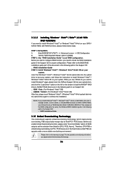
...installation guide part of BIOS setup to set the selection from [Auto] to install Windows?" NOTE. B. page, please insert the ASRock Support CD into your system. Enter BIOS SETUP UTILITY Advanced screen IDE Configuration. Insert the Windows® VistaTM / Windows® VistaTM ...Mode" option of the document in the following path in the Support CD: .. \ RAID Installation Guide 2.15 Untied Overclocking Technology This motherboard supports Untied Overclocking Technology, which means during overclocking, FSB enjoys better margin due to [RAID]. NVIDIA® RAID drivers are in the...
...installation guide part of BIOS setup to set the selection from [Auto] to install Windows?" NOTE. B. page, please insert the ASRock Support CD into your system. Enter BIOS SETUP UTILITY Advanced screen IDE Configuration. Insert the Windows® VistaTM / Windows® VistaTM ...Mode" option of the document in the following path in the Support CD: .. \ RAID Installation Guide 2.15 Untied Overclocking Technology This motherboard supports Untied Overclocking Technology, which means during overclocking, FSB enjoys better margin due to [RAID]. NVIDIA® RAID drivers are in the...

User Manual
Page 27
... press to enter the BIOS SETUP UTILITY after POST, restart the system by pressing + + , or by turning the system off and then back on the motherboard stores the BIOS SETUP UTILITY. You may not exactly match what you start up the security features Exit To exit the current screen or the...
... press to enter the BIOS SETUP UTILITY after POST, restart the system by pressing + + , or by turning the system off and then back on the motherboard stores the BIOS SETUP UTILITY. You may not exactly match what you start up the security features Exit To exit the current screen or the...

