User Manual
Page 5
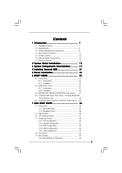
Contents 1 Introduction 7 1.1 Package Contents 7 1.2 Specifications 8 1.3 System Motherboard Components 9 1.4 Rear Panel Connections 11 1.5 System Chassis 12 1.6 Internal System Components 13 1.7 Remote Controller 14 2 System Quick Installation 15 3 System Components Reinstallation 19 4 Installing Second HDD 21 5 Driver Installation 23 6 UTILITY MEMU 24 6.1 Instant Boot 24 6.1.1 Introduction 24 6.1.2 Installation 25 6.2 ASRock OC Tuner 27 6.2.1 Introduction 27...
Contents 1 Introduction 7 1.1 Package Contents 7 1.2 Specifications 8 1.3 System Motherboard Components 9 1.4 Rear Panel Connections 11 1.5 System Chassis 12 1.6 Internal System Components 13 1.7 Remote Controller 14 2 System Quick Installation 15 3 System Components Reinstallation 19 4 Installing Second HDD 21 5 Driver Installation 23 6 UTILITY MEMU 24 6.1 Instant Boot 24 6.1.1 Introduction 24 6.1.2 Installation 25 6.2 ASRock OC Tuner 27 6.2.1 Introduction 27...
User Manual
Page 9
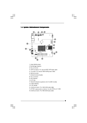
... cable 6. Mini-PCI Express expansion slot: For WiFi module 12. ATX5V output power connector for slim ODD & 2.5" HDD 16. Fan connector 9. CMOS Battery 13. 1.3 System Motherboard Components 16 15 14 13 PCIE1 RoHS 1 2 3 AMCP7AION-HT EuP Ready DDRII_2 FSB800 DDRII_1 4 6 5 12 11 10 9 8 7 1. LPC header 14. SATA connector: For HDD SATA...
... cable 6. Mini-PCI Express expansion slot: For WiFi module 12. ATX5V output power connector for slim ODD & 2.5" HDD 16. Fan connector 9. CMOS Battery 13. 1.3 System Motherboard Components 16 15 14 13 PCIE1 RoHS 1 2 3 AMCP7AION-HT EuP Ready DDRII_2 FSB800 DDRII_1 4 6 5 12 11 10 9 8 7 1. LPC header 14. SATA connector: For HDD SATA...

User Manual
Page 22
Replace the side cover and fasten the screws. 22 Connect one end of SATA and power cables to the ODD and the other end to the top HDD. 7. Connect the other end to SATAII_3 and J1 connectors on the motherboard. 6. Connect the other SATA and power cables to the bottom HDD. 5. 4.
Replace the side cover and fasten the screws. 22 Connect one end of SATA and power cables to the ODD and the other end to the top HDD. 7. Connect the other end to SATAII_3 and J1 connectors on the motherboard. 6. Connect the other SATA and power cables to the bottom HDD. 5. 4.
User Manual
Page 37
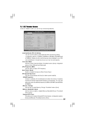
...select Overclock Mode. Cnfiguration options: [Auto], [Manual] and [Optimized]. Memory Bandwidth Boost Use this item to your CPU and motherboard. It should be [Auto] for better system stability. Boot Failure Guard Enable or disable the feature of Boot Failure Guard. The...and [400MHz (DDRII800)]. The default value is [Auo]. Configuration options: [Auto] and [Manual]. The default value is selected, the motherboard will detect the memory module(s) inserted and assigns appropriate frequency automatically. Load Optimized CPU OC Setting You can set up overclocking features. ...
...select Overclock Mode. Cnfiguration options: [Auto], [Manual] and [Optimized]. Memory Bandwidth Boost Use this item to your CPU and motherboard. It should be [Auto] for better system stability. Boot Failure Guard Enable or disable the feature of Boot Failure Guard. The...and [400MHz (DDRII800)]. The default value is [Auo]. Configuration options: [Auto] and [Manual]. The default value is selected, the motherboard will detect the memory module(s) inserted and assigns appropriate frequency automatically. Load Optimized CPU OC Setting You can set up overclocking features. ...

User Manual
Page 42
This option only appears when you set this option to [Enabled] if you plan to use this motherboard to [Auto]. Please set "Suspend to RAM" to submit Windows® VistaTM certification. 42 If [Power Off] is [Disabled]. RTC Alarm Power On Use this ...
This option only appears when you set this option to [Enabled] if you plan to use this motherboard to [Auto]. Please set "Suspend to RAM" to submit Windows® VistaTM certification. 42 If [Power Off] is [Disabled]. RTC Alarm Power On Use this ...
RAID Installation Guide
Page 2
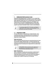
...of data from one logical unit. If you to configure RAID. Although RAID 0 function can start to use RAID 0 or RAID 1 function on this motherboard. RAID 1 (Data Mirroring) RAID 1 is a method combining two or more hard disk drives into one drive to the surviving drive as a single ...drive but at a sustained data transfer rate. This motherboard supports RAID / AHCI function under BIOS environment. It will improve data access and storage since the disk array management software will cause data damage ...
...of data from one logical unit. If you to configure RAID. Although RAID 0 function can start to use RAID 0 or RAID 1 function on this motherboard. RAID 1 (Data Mirroring) RAID 1 is a method combining two or more hard disk drives into one drive to the surviving drive as a single ...drive but at a sustained data transfer rate. This motherboard supports RAID / AHCI function under BIOS environment. It will improve data access and storage since the disk array management software will cause data damage ...
RAID Installation Guide
Page 8
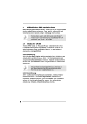
... loss. NVIDIA Windows RAID Installation Guide NVIDIA Windows RAID Installation Guide is a method combining two or more hard disk drives into one logical unit. 2. This motherboard supports RAID / AHCI function under Windows environment.
... loss. NVIDIA Windows RAID Installation Guide NVIDIA Windows RAID Installation Guide is a method combining two or more hard disk drives into one logical unit. 2. This motherboard supports RAID / AHCI function under Windows environment.