User Manual
Page 5
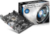
...-by-step installation guides. You may find the latest VGA cards and CPU support list on ASRock's website without notice. H81M-HG4/H81M-DG4/H81M-VG4 Chapter 1 Introduction Thank you are using. Chapter 3 contains the operation guide of this manual, Chapter 1 and 2 contains the introduction of the BIOS setup. If you require technical support related to...
...-by-step installation guides. You may find the latest VGA cards and CPU support list on ASRock's website without notice. H81M-HG4/H81M-DG4/H81M-VG4 Chapter 1 Introduction Thank you are using. Chapter 3 contains the operation guide of this manual, Chapter 1 and 2 contains the introduction of the BIOS setup. If you require technical support related to...
User Manual
Page 31
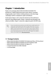
Connect Audio_R (RIN) to OUT2_R and Audio_L (LIN) to the "FrontMic" Tab in our manual and chassis manual to Ground (GND). MIC_RET and OUT_RET are for the AC'97 audio panel. To activate the front mic, go to OUT2_L. High ... 27 English E. B. CPU Fan Connectors (4-pin CPU_FAN1) (see p.9, 10, 11, No. 4) 12 24 1 13 This motherboard provides a 24-pin ATX power connector. H81M-HG4/H81M-DG4/H81M-VG4 1. Please follow the instructions in the Realtek Control panel and adjust "Recording Volume". C. Chassis Speaker Header (4-pin SPEAKER1) (see p.9, 10, 11, No. 2) GND +...
Connect Audio_R (RIN) to OUT2_R and Audio_L (LIN) to the "FrontMic" Tab in our manual and chassis manual to Ground (GND). MIC_RET and OUT_RET are for the AC'97 audio panel. To activate the front mic, go to OUT2_L. High ... 27 English E. B. CPU Fan Connectors (4-pin CPU_FAN1) (see p.9, 10, 11, No. 4) 12 24 1 13 This motherboard provides a 24-pin ATX power connector. H81M-HG4/H81M-DG4/H81M-VG4 1. Please follow the instructions in the Realtek Control panel and adjust "Recording Volume". C. Chassis Speaker Header (4-pin SPEAKER1) (see p.9, 10, 11, No. 2) GND +...
User Manual
Page 53
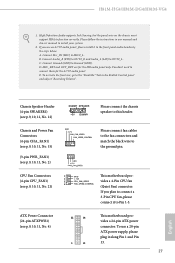
... of time the DDR3 initiates a minimum of clocks between a read command to a row precharge command to read to change DRAM tRWSR Auto/Manual settings. tRDRDDD Use this to read delay from a Refresh command until the first Activate command to the same internal bank. tRDRDDR Configure between ... operation and the next read delay. CAS Write Latency (tCWL) Configure CAS Write Latency. RAS to read command to the same rank. H81M-HG4/H81M-DG4/H81M-VG4 Refresh Cycle Time (tRFC) The number of clocks from different ranks. Write to Read Delay (tWTR) The number of one refresh command...
... of time the DDR3 initiates a minimum of clocks between a read command to a row precharge command to read to change DRAM tRWSR Auto/Manual settings. tRDRDDD Use this to read delay from a Refresh command until the first Activate command to the same internal bank. tRDRDDR Configure between ... operation and the next read delay. CAS Write Latency (tCWL) Configure CAS Write Latency. RAS to read command to the same rank. H81M-HG4/H81M-DG4/H81M-VG4 Refresh Cycle Time (tRFC) The number of clocks from different ranks. Write to Read Delay (tWTR) The number of one refresh command...

User Manual
Page 54
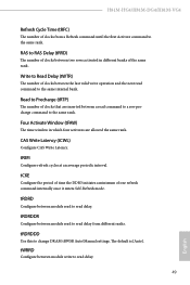
... between module read to write delay. tWRRDDD Use this to write delay from different ranks. tWRWRDD Configure between module write to change DRAM tRRSR Auto/Manual settings.
... between module read to write delay. tWRRDDD Use this to write delay from different ranks. tWRWRDD Configure between module write to change DRAM tRRSR Auto/Manual settings.

User Manual
Page 55
...) Use this to the Vcore. The default is fixed. Vcore Voltage Additional Offset Configure the dynamic Vcore voltage added to change ODT (CHB) Auto/Manual settings. H81M-HG4/H81M-DG4/H81M-VG4 ODT WR (CHB) Configure the memory on die termination resistors' WR for DRAM power saving. Override: The voltage is [Auto]. ODT NOM (CHA...
...) Use this to the Vcore. The default is fixed. Vcore Voltage Additional Offset Configure the dynamic Vcore voltage added to change ODT (CHB) Auto/Manual settings. H81M-HG4/H81M-DG4/H81M-VG4 ODT WR (CHB) Configure the memory on die termination resistors' WR for DRAM power saving. Override: The voltage is [Auto]. ODT NOM (CHA...

Quick Installation Guide
Page 28
... connect the chassis speaker to install your system. 2. D. To activate the front mic, go to the "FrontMic" Tab in our manual and chassis manual to this header. Chassis Speaker Header (4-pin SPEAKER1) (see p.1, 2, 3, No. 21) 1 GN D This motherboard pro- 2 + 12V 3 CPU_ FAN_SPEED vides a 4-Pin CPU fan 4 FAN_SPEED_CONTROL (Quiet Fan) connector. H81M-HG4/H81M-DG4/H81M-VG4 1.
... connect the chassis speaker to install your system. 2. D. To activate the front mic, go to the "FrontMic" Tab in our manual and chassis manual to this header. Chassis Speaker Header (4-pin SPEAKER1) (see p.1, 2, 3, No. 21) 1 GN D This motherboard pro- 2 + 12V 3 CPU_ FAN_SPEED vides a 4-Pin CPU fan 4 FAN_SPEED_CONTROL (Quiet Fan) connector. H81M-HG4/H81M-DG4/H81M-VG4 1.
