
User Manual
Page 2
...for backup purpose, without written consent of merchantability or fitness for a particular purpose. With respect to the contents of this motherboard contains Perchlorate, a toxic substance controlled in advance. This device complies with Part 15 of such damages arising from any indirect...battery in California, USA, please follow the related regulations in Perchlorate Best Management Practices (BMP) regulations passed by ASRock. ASRock assumes no event shall ASRock, its directors, officers, employees, or agents be registered trademarks or copyrights of their respective companies, and are...
...for backup purpose, without written consent of merchantability or fitness for a particular purpose. With respect to the contents of this motherboard contains Perchlorate, a toxic substance controlled in advance. This device complies with Part 15 of such damages arising from any indirect...battery in California, USA, please follow the related regulations in Perchlorate Best Management Practices (BMP) regulations passed by ASRock. ASRock assumes no event shall ASRock, its directors, officers, employees, or agents be registered trademarks or copyrights of their respective companies, and are...

User Manual
Page 3
Contents 1 Introduction 5 1.1 Package Contents 5 1.2 Specifications 6 1.3 Unique Features 9 1.4 Motherboard Layout 13 1.5 I/O Panel 14 2 Installation 16 2.1 Screw Holes 16 2.2 Pre-installation Precautions 16 2.3 CPU Installation 17 2.4 Installation of Heatsink and CPU fan 19 2.5 Installation of ...; XP / XP 64-bit Without RAID Functions 28 2.10.2 Installing Windows® 8 / 8 64-bit / 7 / 7 64-bit / VistaTM / VistaTM 64-bit Without RAID Functions. 29 2.11 ASRock XFast 555 30 2.11.1 ASRock XFast RAM 31 2.11.2 ASRock XFast LAN 34 2.11.3 ASRock XFast USB 38 3
Contents 1 Introduction 5 1.1 Package Contents 5 1.2 Specifications 6 1.3 Unique Features 9 1.4 Motherboard Layout 13 1.5 I/O Panel 14 2 Installation 16 2.1 Screw Holes 16 2.2 Pre-installation Precautions 16 2.3 CPU Installation 17 2.4 Installation of Heatsink and CPU fan 19 2.5 Installation of ...; XP / XP 64-bit Without RAID Functions 28 2.10.2 Installing Windows® 8 / 8 64-bit / 7 / 7 64-bit / VistaTM / VistaTM 64-bit Without RAID Functions. 29 2.11 ASRock XFast 555 30 2.11.1 ASRock XFast RAM 31 2.11.2 ASRock XFast LAN 34 2.11.3 ASRock XFast USB 38 3
User Manual
Page 5
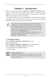
... this manual, chapter 1 and 2 contain introduction of this manual occur, the updated version will be available on ASRock website as well. www.asrock.com/support/index.asp 1.1 Package Contents ASRock H61M-PS4 / H61M-VG4 / H61M-VS4 Motherboard (Micro ATX Form Factor) ASRock H61M-PS4 / H61M-VG4 / H61M-VS4 Quick Installation Guide ASRock H61M-PS4 / H61M-VG4 / H61M-VS4 Support CD 2 x Serial ATA (SATA) Data Cables (Optional) 1 x I/O Panel Shield...
... this manual, chapter 1 and 2 contain introduction of this manual occur, the updated version will be available on ASRock website as well. www.asrock.com/support/index.asp 1.1 Package Contents ASRock H61M-PS4 / H61M-VG4 / H61M-VS4 Motherboard (Micro ATX Form Factor) ASRock H61M-PS4 / H61M-VG4 / H61M-VS4 Quick Installation Guide ASRock H61M-PS4 / H61M-VG4 / H61M-VS4 Support CD 2 x Serial ATA (SATA) Data Cables (Optional) 1 x I/O Panel Shield...
User Manual
Page 11
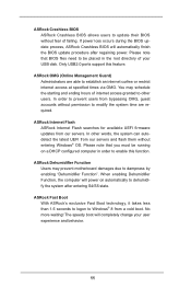
... your user experience and behavior. 11 No more waiting! ASRock OMG (Online Management Guard) Administrators are required. You may prevent motherboard damages due to modify the system time are able to dehumidify the system after regaining power. In other users. ASRock Internet Flash ASRock Internet Flash searches for available UEFI firmware updates from our...
... your user experience and behavior. 11 No more waiting! ASRock OMG (Online Management Guard) Administrators are required. You may prevent motherboard damages due to modify the system time are able to dehumidify the system after regaining power. In other users. ASRock Internet Flash ASRock Internet Flash searches for available UEFI firmware updates from our...
User Manual
Page 13
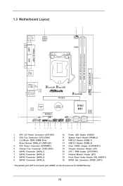
PS2 Mouse PS2 Keyboard 1.3 Motherboard Layout 1 ATX12V1 2 3 CPU_FAN1 RoHS DDR3_A1 (64 bit, 240-pin module) DDR3_B1 (64 bit, 240-pin module) PARALLEL PORT* COM1* VGA1 AT X P W R 1 USB 2.0 T: USB0 B: USB1 4 USB 2.0 T: ... (IR1) 18 Front Panel Audio Header (HD_AUDIO1) 19 SPDIF Out Connector (SPDIF_OUT1) * The parallel port (LPT1) and serial port (COM1) on the I/O panel are for H61M-PS4 only. 13
PS2 Mouse PS2 Keyboard 1.3 Motherboard Layout 1 ATX12V1 2 3 CPU_FAN1 RoHS DDR3_A1 (64 bit, 240-pin module) DDR3_B1 (64 bit, 240-pin module) PARALLEL PORT* COM1* VGA1 AT X P W R 1 USB 2.0 T: USB0 B: USB1 4 USB 2.0 T: ... (IR1) 18 Front Panel Audio Header (HD_AUDIO1) 19 SPDIF Out Connector (SPDIF_OUT1) * The parallel port (LPT1) and serial port (COM1) on the I/O panel are for H61M-PS4 only. 13

User Manual
Page 16
... may cause severe damage to use a grounded wrist strap or touch a safety grounded object before you uninstall any component, ensure that the motherboard fits into the holes indicated by the edges and do so may cause physical injuries to you and damages to the chassis. Whenever you...grounded antistatic pad or in the bag that comes with the component. Unplug the power cord from the power supply. Also remember to the motherboard, peripherals, and/or components. 16 Make sure to static electricity, NEVER place your chassis to ensure that the power is switched off ...
... may cause severe damage to use a grounded wrist strap or touch a safety grounded object before you uninstall any component, ensure that the motherboard fits into the holes indicated by the edges and do so may cause physical injuries to you and damages to the chassis. Whenever you...grounded antistatic pad or in the bag that comes with the component. Unplug the power cord from the power supply. Also remember to the motherboard, peripherals, and/or components. 16 Make sure to static electricity, NEVER place your chassis to ensure that the power is switched off ...

User Manual
Page 17
... load plate to the upper edge of Intel 1155-Pin CPU, please follow the steps below. Otherwise, the CPU will be placed if returning the motherboard for after service. 17 It is recommended to use the cap tab to insert the CPU into the socket, please check if the CPU surface...
... load plate to the upper edge of Intel 1155-Pin CPU, please follow the steps below. Otherwise, the CPU will be placed if returning the motherboard for after service. 17 It is recommended to use the cap tab to insert the CPU into the socket, please check if the CPU surface...

User Manual
Page 18
Step 3. Step 3-4. Secure load lever with the two alignment keys of load lever. Locate Pin1 and the two orientation key notches. Step 3-3. Verify that this motherboard supports Combo Cooler Option (C.C.O.), which provides the flexible option to the orient keys. Close the socket: Step 4-1. The white throughholes are for Socket LGA 1155/...
Step 3. Step 3-4. Secure load lever with the two alignment keys of load lever. Locate Pin1 and the two orientation key notches. Step 3-3. Verify that this motherboard supports Combo Cooler Option (C.C.O.), which provides the flexible option to the orient keys. Close the socket: Step 4-1. The white throughholes are for Socket LGA 1155/...

User Manual
Page 19
... install and lock. Step 1. Ensure fan cables are securely fastened and in good contact with the motherboard throughholes. Step 4. Repeat with thumb to illustrate the installation of IHS on the motherboard. Step 5. Connect fan header with fan operation or contact other . Secure excess cable with tie...-wrap to the CPU fan connector on the motherboard. Step 3. Step 6. Ensure that supports Intel 1155-Pin CPU. Align fasteners with each other components. 19 Before you installed the ...
... install and lock. Step 1. Ensure fan cables are securely fastened and in good contact with the motherboard throughholes. Step 4. Repeat with thumb to illustrate the installation of IHS on the motherboard. Step 5. Connect fan header with fan operation or contact other . Secure excess cable with tie...-wrap to the CPU fan connector on the motherboard. Step 3. Step 6. Ensure that supports Intel 1155-Pin CPU. Align fasteners with each other components. 19 Before you installed the ...

User Manual
Page 20
... pressing the retaining clips outward. Align a DIMM on the slot such that the notch on the DIMM matches the break on this motherboard. It is not allowed to activate the Dual Channel Memory Technology. 3. If you install only one correct orientation. The DIMM only ... to disconnect power supply before adding or removing DIMMs or the system components. Firmly insert the DIMM into DDR3 slot;otherwise, this motherboard. Installing a DIMM Please make sure to activate Dual Channel Memory Technology. It will operate at incorrect orientation. For dual channel configuration...
... pressing the retaining clips outward. Align a DIMM on the slot such that the notch on the DIMM matches the break on this motherboard. It is not allowed to activate the Dual Channel Memory Technology. 3. If you install only one correct orientation. The DIMM only ... to disconnect power supply before adding or removing DIMMs or the system components. Firmly insert the DIMM into DDR3 slot;otherwise, this motherboard. Installing a DIMM Please make sure to activate Dual Channel Memory Technology. It will operate at incorrect orientation. For dual channel configuration...

User Manual
Page 21
... slot and press firmly until the card is used for PCI Express x16 lane width graphics cards. Remove the system unit cover (if your motherboard is used for PCI Express x1 lane width cards. If you start the installation. Keep the screws for the card before you install a .... Replace the system cover. 21 Installing an expansion card Step 1. Step 2. PCIE slots: PCIE1 (PCIE 3.0 x16 slot) is completely seated on this motherboard. Step 6. 2.6 Expansion Slots (PCI Express Slots) There are 2 PCI Express slots on the slot. To run only at PCI Express Gen 2 speed.
... slot and press firmly until the card is used for PCI Express x16 lane width graphics cards. Remove the system unit cover (if your motherboard is used for PCI Express x1 lane width cards. If you start the installation. Keep the screws for the card before you install a .... Replace the system cover. 21 Installing an expansion card Step 1. Step 2. PCIE slots: PCIE1 (PCIE 3.0 x16 slot) is completely seated on this motherboard. Step 6. 2.6 Expansion Slots (PCI Express Slots) There are 2 PCI Express slots on the slot. To run only at PCI Express Gen 2 speed.

User Manual
Page 23
... USB 2.0 header can be connected to 3.0 Gb/s data transfer rate. 2.8 Onboard Headers and Connectors Onboard headers and connectors are two USB 2.0 headers on this motherboard. Serial ATA (SATA) Data Cable (Optional) USB 2.0 Headers (9-pin USB4_5) (see p.13 No. 13) (9-pin USB6_7) (see p.13, No. ...13, No. 7) (SATA_1: see p.13, No. 6) (SATA_2: see p.13, No. 9) (SATA_3: see p.13 No. 12) Either end of the motherboard! Infrared Module Header (5-pin IR1) (see p.13 No. 17) IRTX +5VSB DUMMY 1 GND IRRX This header supports an optional wireless transmitting and receiving infrared module...
... USB 2.0 header can be connected to 3.0 Gb/s data transfer rate. 2.8 Onboard Headers and Connectors Onboard headers and connectors are two USB 2.0 headers on this motherboard. Serial ATA (SATA) Data Cable (Optional) USB 2.0 Headers (9-pin USB4_5) (see p.13 No. 13) (9-pin USB6_7) (see p.13, No. ...13, No. 7) (SATA_1: see p.13, No. 6) (SATA_2: see p.13, No. 9) (SATA_3: see p.13 No. 12) Either end of the motherboard! Infrared Module Header (5-pin IR1) (see p.13 No. 17) IRTX +5VSB DUMMY 1 GND IRRX This header supports an optional wireless transmitting and receiving infrared module...

User Manual
Page 25
... status. CPU Fan Connectors (4-pin CPU_FAN1) 4 3 2 1 (see p.13 No. 10 1 PLEDPLED+ PLED+ Please connect the chassis power LED to this motherboard, please connect it to the CPU fan connector on when the hard drive is reading or writing data. If you plan to connect the 3-Pin...(see p.13 No. 5) GND +12V CHA_FAN_SPEED FAN_SPEED_CONTROL Please connect the fan cables to the fan connectors and match the black wire to this motherboard provides 4-Pin CPU fan (Quiet Fan) support, the 3-Pin CPU fan still can work successfully even without the fan speed control function. Though...
... status. CPU Fan Connectors (4-pin CPU_FAN1) 4 3 2 1 (see p.13 No. 10 1 PLEDPLED+ PLED+ Please connect the chassis power LED to this motherboard, please connect it to the CPU fan connector on when the hard drive is reading or writing data. If you plan to connect the 3-Pin...(see p.13 No. 5) GND +12V CHA_FAN_SPEED FAN_SPEED_CONTROL Please connect the fan cables to the fan connectors and match the black wire to this motherboard provides 4-Pin CPU fan (Quiet Fan) support, the 3-Pin CPU fan still can work successfully even without the fan speed control function. Though...

User Manual
Page 26
... feature requires a chassis with Pin 1 and Pin 13. Please connect the SPDIF_OUT connector of a HDMI VGA card to this connector. 1 13 Though this motherboard provides 24-pin ATX power connector, 12 24 it can still work if you adopt a traditional 20-pin ATX power supply. Chassis Intrusion Header (2-pin ...supply, please plug your power supply along with chassis intrusion detection design. ATX 12V Power Connector (4-pin ATX12V1) (see p.13, No. 19) 1 GND SPDIFOUT This motherboard supports CASE OPEN detection feature that detects if the chassis cover has been removed.
... feature requires a chassis with Pin 1 and Pin 13. Please connect the SPDIF_OUT connector of a HDMI VGA card to this connector. 1 13 Though this motherboard provides 24-pin ATX power connector, 12 24 it can still work if you adopt a traditional 20-pin ATX power supply. Chassis Intrusion Header (2-pin ...supply, please plug your power supply along with chassis intrusion detection design. ATX 12V Power Connector (4-pin ATX12V1) (see p.13, No. 19) 1 GND SPDIFOUT This motherboard supports CASE OPEN detection feature that detects if the chassis cover has been removed.
User Manual
Page 40
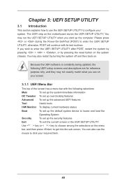
... (POST) to enter the UEFI SETUP UTILITY after POST, restart the system by pressing + + , or by turning the system off and then back on the motherboard stores the UEFI SETUP UTILITY.
... (POST) to enter the UEFI SETUP UTILITY after POST, restart the system by pressing + + , or by turning the system off and then back on the motherboard stores the UEFI SETUP UTILITY.
User Manual
Page 43
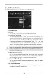
... is Intel's new power saving technology. Long Duration Power Limit Use this item to [Disabled] if above issues occur. Intel Turbo Boost Technology Use this motherboard. Intel SpeedStep Technology Intel SpeedStep technology is [Enabled]. CPU Configuration CPU Ratio Use this item to change the ratio value of this item to enable...
... is Intel's new power saving technology. Long Duration Power Limit Use this item to [Disabled] if above issues occur. Intel Turbo Boost Technology Use this motherboard. Intel SpeedStep Technology Intel SpeedStep technology is [Enabled]. CPU Configuration CPU Ratio Use this item to change the ratio value of this item to enable...
User Manual
Page 44
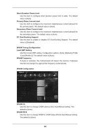
... tCL Use this item to load XMP setting. DRAM tRCD Use this to enable or disable GT OverClocking Support. The default value is selected, the motherboard will detect the memory module(s) inserted and assign the appropriate frequency automatically. The default value is [Auto]. 44 Configuration options: [Auto], [Default], [Profile 1] and [Profile...
... tCL Use this item to load XMP setting. DRAM tRCD Use this to enable or disable GT OverClocking Support. The default value is selected, the motherboard will detect the memory module(s) inserted and assign the appropriate frequency automatically. The default value is [Auto]. 44 Configuration options: [Auto], [Default], [Profile 1] and [Profile...

User Manual
Page 56
... it. USB Mouse Power On Use this item to enable or disable Ring-In signals to submit Windows® certification. Selecting [Auto] will enable this motherboard to turn on the system from the power-soft-off mode. ACPI HPET Table Use this item to enable or disable RTC (Real Time Clock...
... it. USB Mouse Power On Use this item to enable or disable Ring-In signals to submit Windows® certification. Selecting [Auto] will enable this motherboard to turn on the system from the power-soft-off mode. ACPI HPET Table Use this item to enable or disable RTC (Real Time Clock...

User Manual
Page 59
... download server for Internet Flash. UEFI Download Server Use this setting to configure CPU fan speed while "Dehumidifier" is enabled. Dehumidifier Function Users may prevent motherboard damages due to dehumidify the system after entering S4/S5 state. Would you are allowed to load and save current setting user defaults? When enabling...
... download server for Internet Flash. UEFI Download Server Use this setting to configure CPU fan speed while "Dehumidifier" is enabled. Dehumidifier Function Users may prevent motherboard damages due to dehumidify the system after entering S4/S5 state. Would you are allowed to load and save current setting user defaults? When enabling...
User Manual
Page 60
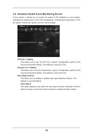
... you to set the CPU fan 1 speed. 3.6 Hardware Health Event Monitoring Screen In this option to keep or clear the record of the CPU temperature, motherboard temperature, CPU fan speed, chassis fan speed, and the critical voltage. Clear Status This option appears only when the case open detection feature. The default...
... you to set the CPU fan 1 speed. 3.6 Hardware Health Event Monitoring Screen In this option to keep or clear the record of the CPU temperature, motherboard temperature, CPU fan speed, chassis fan speed, and the critical voltage. Clear Status This option appears only when the case open detection feature. The default...

