User Manual
Page 6
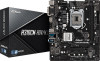
ASRock website http://www.asrock.com. 1.1 Package Contents • ASRock H310CM-HDV/M.2 Motherboard (Micro ATX Form Factor) • ASRock H310CM-HDV/M.2 Quick Installation Guide • ASRock H310CM-HDV/M.2 Support CD • 1 x I/O Panel Shield • 2 x Serial ATA (SATA) Data Cables (Optional) • 1 x Screw for purchasing ASRock H310CM-HDV/M.2 motherboard, a reliable motherboard produced under ASRock's consistently stringent quality control. Chapter 3 contains the operation guide of the motherboard and step-by-step installation...
ASRock website http://www.asrock.com. 1.1 Package Contents • ASRock H310CM-HDV/M.2 Motherboard (Micro ATX Form Factor) • ASRock H310CM-HDV/M.2 Quick Installation Guide • ASRock H310CM-HDV/M.2 Support CD • 1 x I/O Panel Shield • 2 x Serial ATA (SATA) Data Cables (Optional) • 1 x Screw for purchasing ASRock H310CM-HDV/M.2 motherboard, a reliable motherboard produced under ASRock's consistently stringent quality control. Chapter 3 contains the operation guide of the motherboard and step-by-step installation...
User Manual
Page 11
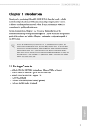
... 1.3 Motherboard Layout 1 ATX12V1 2 3 4 CPU_FAN1 CHA_FAN1/WP 5 VGA1 DVI1 ATXPWR1 DDR4_A1 (64 bit, 288-pin module) DDR4_B1 (64 bit, 288-pin module) HDMI1 USB 3.1 Gen1 T: USB3 B: USB4 USB 2.0 T: USB5 B: USB6 Top: RJ-45 LAN Intel H310 CMOS Battery 6 1 1 7 USB_11_12 USB_9_10 Top: LINE IN Center: FRONT Bottom: MIC IN PCIE1 8 BIOS ROM H310CM-HDV/M.2 9 SATA3_3...
... 1.3 Motherboard Layout 1 ATX12V1 2 3 4 CPU_FAN1 CHA_FAN1/WP 5 VGA1 DVI1 ATXPWR1 DDR4_A1 (64 bit, 288-pin module) DDR4_B1 (64 bit, 288-pin module) HDMI1 USB 3.1 Gen1 T: USB3 B: USB4 USB 2.0 T: USB5 B: USB6 Top: RJ-45 LAN Intel H310 CMOS Battery 6 1 1 7 USB_11_12 USB_9_10 Top: LINE IN Center: FRONT Bottom: MIC IN PCIE1 8 BIOS ROM H310CM-HDV/M.2 9 SATA3_3...

User Manual
Page 18
The cover must be placed if you wish to return the motherboard for after service. 13 English H310CM-HDV/M.2 Please save and replace the cover if the processor is removed.
The cover must be placed if you wish to return the motherboard for after service. 13 English H310CM-HDV/M.2 Please save and replace the cover if the processor is removed.
User Manual
Page 20
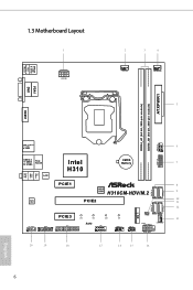
It is unable to install identical (the same brand, speed, size and chip-type) DDR4 DIMM pairs. 2. otherwise, this motherboard and DIMM may be damaged. The DIMM only fits in one memory module installed. 3. It will cause permanent damage to install a DDR, DDR2 or ...DDR3 memory module into the slot at incorrect orientation. 15 English It is not allowed to the motherboard and the DIMM if you always need to activate Dual Channel Memory Technology with only one correct orientation. For dual channel configuration, you force the...
It is unable to install identical (the same brand, speed, size and chip-type) DDR4 DIMM pairs. 2. otherwise, this motherboard and DIMM may be damaged. The DIMM only fits in one memory module installed. 3. It will cause permanent damage to install a DDR, DDR2 or ...DDR3 memory module into the slot at incorrect orientation. 15 English It is not allowed to the motherboard and the DIMM if you always need to activate Dual Channel Memory Technology with only one correct orientation. For dual channel configuration, you force the...
User Manual
Page 22
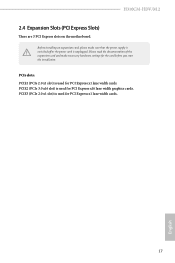
... Express x1 lane width cards. PCIE2 (PCIe 3.0 x16 slot) is used for the card before you start the installation. H310CM-HDV/M.2 2.4 Expansion Slots (PCI Express Slots) There are 3 PCI Express slots on the motherboard. Please read the documentation of the expansion card and make sure that the power supply is switched off or...
... Express x1 lane width cards. PCIE2 (PCIe 3.0 x16 slot) is used for the card before you start the installation. H310CM-HDV/M.2 2.4 Expansion Slots (PCI Express Slots) There are 3 PCI Express slots on the motherboard. Please read the documentation of the expansion card and make sure that the power supply is switched off or...
User Manual
Page 24
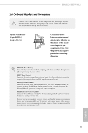
...reading or writing data. English 19 A front panel module mainly consists of power button, reset button, power LED, hard drive activity LED, speaker and etc. H310CM-HDV/M.2 2.6 Onboard Headers and Connectors Onboard headers and connectors are matched correctly. PWRBTN (Power Button): Connect to perform a normal restart. RESET (Reset Button): Connect to... the reset button on the chassis front panel. The front panel design may configure the way to the motherboard. Note the positive and negative pins before connecting the cables.
...reading or writing data. English 19 A front panel module mainly consists of power button, reset button, power LED, hard drive activity LED, speaker and etc. H310CM-HDV/M.2 2.6 Onboard Headers and Connectors Onboard headers and connectors are matched correctly. PWRBTN (Power Button): Connect to perform a normal restart. RESET (Reset Button): Connect to... the reset button on the chassis front panel. The front panel design may configure the way to the motherboard. Note the positive and negative pins before connecting the cables.
User Manual
Page 26
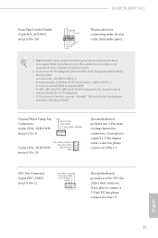
...Pin 1-3. English 21 Connect Ground (GND) to function correctly. You don't need to Pin 1-3. H310CM-HDV/M.2 Front Panel Audio Header (9-pin HD_AUDIO1) (see p.6, No. 2) FAN_SPEED_CONTROL CPU_FAN_SPEED FAN_VOLTAGE GND 1 2 34 This motherboard provides a 4-Pin CPU fan (Quiet Fan) connector. High Definition Audio supports Jack Sensing, but...(see p.6, No. 4) GND FAN_VOLTAGE FAN_SPEED FAN_SPEED_CONTROL 1 2 34 FAN_SPEED_CONTROL 4 CHA_FAN_SPEED 3 (4-pin CHA_FAN2/WP) FAN_VOLTAGE 2 GND 1 (see p.6, No. 13) This motherboard provides two 4-Pin water cooling chassis fan connectors.
...Pin 1-3. English 21 Connect Ground (GND) to function correctly. You don't need to Pin 1-3. H310CM-HDV/M.2 Front Panel Audio Header (9-pin HD_AUDIO1) (see p.6, No. 2) FAN_SPEED_CONTROL CPU_FAN_SPEED FAN_VOLTAGE GND 1 2 34 This motherboard provides a 4-Pin CPU fan (Quiet Fan) connector. High Definition Audio supports Jack Sensing, but...(see p.6, No. 4) GND FAN_VOLTAGE FAN_SPEED FAN_SPEED_CONTROL 1 2 34 FAN_SPEED_CONTROL 4 CHA_FAN_SPEED 3 (4-pin CHA_FAN2/WP) FAN_VOLTAGE 2 GND 1 (see p.6, No. 13) This motherboard provides two 4-Pin water cooling chassis fan connectors.
User Manual
Page 48
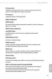
.... DRAM Reference Clock Select Auto for memory training. DRAM Frequency If [Auto] is disabled. DRAM Clock controls memory training only if ASRock Timing Optimization is selected, the motherboard will detect the memory module(s) inserted and assign the appropriate frequency automatically. Primary Timing CAS# Latency (tCL) The time between sending ...# to clock delay for optimized settings. Row Precharge: The number of clock cycles required between the opening the next row. 43 English H310CM-HDV/M.2 GT Current Limit Configure the current limit of memory and accessing columns within it.
.... DRAM Reference Clock Select Auto for memory training. DRAM Frequency If [Auto] is disabled. DRAM Clock controls memory training only if ASRock Timing Optimization is selected, the motherboard will detect the memory module(s) inserted and assign the appropriate frequency automatically. Primary Timing CAS# Latency (tCL) The time between sending ...# to clock delay for optimized settings. Row Precharge: The number of clock cycles required between the opening the next row. 43 English H310CM-HDV/M.2 GT Current Limit Configure the current limit of memory and accessing columns within it.
User Manual
Page 68
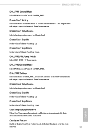
... Fan 1, or choose Customize to detect whether the chassis cover has been removed. 63 English Chassis Fan 2 Temp Source Select a fan temperature source for CHA_FAN1. H310CM-HDV/M.2 CHA_FAN1 Control Mode Select PWM mode or DC mode for Chassis Fan 2. Over Temperature Protection When Over Temperature Protection is enabled, the system automatically shuts...
... Fan 1, or choose Customize to detect whether the chassis cover has been removed. 63 English Chassis Fan 2 Temp Source Select a fan temperature source for CHA_FAN1. H310CM-HDV/M.2 CHA_FAN1 Control Mode Select PWM mode or DC mode for Chassis Fan 2. Over Temperature Protection When Over Temperature Protection is enabled, the system automatically shuts...
User Manual
Page 75
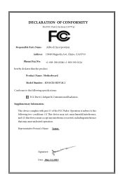
... Rules. DECLARATION OF CONFORMITY Per FCC Part 2 Section 2.1077(a) Responsible Party Name: ASRock Incorporation Address: 13848 Magnolia Ave, Chino, CA91710 Phone/Fax No: +1-909-590-8308/+1-909-590-1026 hereby declares that the product Product Name : Motherboard Model Number : H310CM-HDV/M.2 Conforms to the following speci cations: FCC Part15, SubpartB,Unintentional Radiators Supplementary Information...
... Rules. DECLARATION OF CONFORMITY Per FCC Part 2 Section 2.1077(a) Responsible Party Name: ASRock Incorporation Address: 13848 Magnolia Ave, Chino, CA91710 Phone/Fax No: +1-909-590-8308/+1-909-590-1026 hereby declares that the product Product Name : Motherboard Model Number : H310CM-HDV/M.2 Conforms to the following speci cations: FCC Part15, SubpartB,Unintentional Radiators Supplementary Information...
User Manual
Page 76
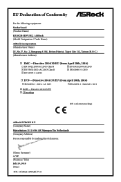
... for making this declaration: (Name, Surname) A.V.P (Position / Title) July 20, 2018 (Date) P/N: 15G062111000AK V1.0 EU Declaration of Conformity For the following equipment: Motherboard (Product Name) H310CM-HDV/M.2 / ASRock (Model Designation / Trade Name) ASRock Incorporation (Manufacturer Name) 2F., No.37, Sec. 2, Jhongyang S. Rd., Beitou District, Taipei City 112, Taiwan (R.O.C.) (Manufacturer Address) ڛEMC -Directive...
... for making this declaration: (Name, Surname) A.V.P (Position / Title) July 20, 2018 (Date) P/N: 15G062111000AK V1.0 EU Declaration of Conformity For the following equipment: Motherboard (Product Name) H310CM-HDV/M.2 / ASRock (Model Designation / Trade Name) ASRock Incorporation (Manufacturer Name) 2F., No.37, Sec. 2, Jhongyang S. Rd., Beitou District, Taipei City 112, Taiwan (R.O.C.) (Manufacturer Address) ڛEMC -Directive...


