
User Manual
Page 2
... may not cause harmful interference, and (2) this documentation may or may apply, see www.dtsc.ca.gov/hazardouswaste/ perchlorate" ASRock Website: http://www.asrock.com "Perchlorate Material-special handling may not be constructed as a commitment by any kind, either expressed or implied, including but...interference that may cause undesired operation. All rights reserved. Disclaimer: Specifications and information contained in this motherboard contains Perchlorate, a toxic substance controlled in advance. CALIFORNIA, USA ONLY The Lithium battery adopted on this documentation.
... may not cause harmful interference, and (2) this documentation may or may apply, see www.dtsc.ca.gov/hazardouswaste/ perchlorate" ASRock Website: http://www.asrock.com "Perchlorate Material-special handling may not be constructed as a commitment by any kind, either expressed or implied, including but...interference that may cause undesired operation. All rights reserved. Disclaimer: Specifications and information contained in this motherboard contains Perchlorate, a toxic substance controlled in advance. CALIFORNIA, USA ONLY The Lithium battery adopted on this documentation.

User Manual
Page 4
... Contents 1 1.2 Specifications 2 1.3 Motherboard Layout 6 1.4 I/O Panel 8 Chapter 2 Installation 10 2.1 Installing the CPU 11 2.2 Installing the CPU Fan and Heatsink 14 2.3 Installing Memory Modules (DIMM) 15 2.4 Expansion Slots (PCI Express Slots) 17 2.5 Jumpers Setup 18 2.6 Onboard Headers and Connectors 19 Chapter 3 Software and Utilities Operation 26 3.1 Installing Drivers 26 3.2 A-Tuning 27 3.3 ASRock Live Update...
... Contents 1 1.2 Specifications 2 1.3 Motherboard Layout 6 1.4 I/O Panel 8 Chapter 2 Installation 10 2.1 Installing the CPU 11 2.2 Installing the CPU Fan and Heatsink 14 2.3 Installing Memory Modules (DIMM) 15 2.4 Expansion Slots (PCI Express Slots) 17 2.5 Jumpers Setup 18 2.6 Onboard Headers and Connectors 19 Chapter 3 Software and Utilities Operation 26 3.1 Installing Drivers 26 3.2 A-Tuning 27 3.3 ASRock Live Update...
User Manual
Page 6
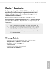
...://www.asrock.com. 1.1 Package Contents • ASRock H310CM-HDV/M.2 Motherboard (Micro ATX Form Factor) • ASRock H310CM-HDV/M.2 Quick Installation Guide • ASRock H310CM-HDV/M.2 Support CD • 1 x I/O Panel Shield • 2 x Serial ATA (SATA) Data Cables (Optional) • 1 x Screw for purchasing ASRock H310CM-HDV/M.2 motherboard, a reliable motherboard produced under ASRock's consistently stringent quality control. You may find the latest VGA cards and CPU support list on ASRock's website...
...://www.asrock.com. 1.1 Package Contents • ASRock H310CM-HDV/M.2 Motherboard (Micro ATX Form Factor) • ASRock H310CM-HDV/M.2 Quick Installation Guide • ASRock H310CM-HDV/M.2 Support CD • 1 x I/O Panel Shield • 2 x Serial ATA (SATA) Data Cables (Optional) • 1 x Screw for purchasing ASRock H310CM-HDV/M.2 motherboard, a reliable motherboard produced under ASRock's consistently stringent quality control. You may find the latest VGA cards and CPU support list on ASRock's website...
User Manual
Page 11
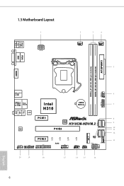
... 1.3 Motherboard Layout 1 ATX12V1 2 3 4 CPU_FAN1 CHA_FAN1/WP 5 VGA1 DVI1 ATXPWR1 DDR4_A1 (64 bit, 288-pin module) DDR4_B1 (64 bit, 288-pin module) HDMI1 USB 3.1 Gen1 T: USB3 B: USB4 USB 2.0 T: USB5 B: USB6 Top: RJ-45 LAN Intel H310 CMOS Battery 6 1 1 7 USB_11_12 USB_9_10 Top: LINE IN Center: FRONT Bottom: MIC IN PCIE1 8 BIOS ROM H310CM-HDV/M.2 9 SATA3_3...
... 1.3 Motherboard Layout 1 ATX12V1 2 3 4 CPU_FAN1 CHA_FAN1/WP 5 VGA1 DVI1 ATXPWR1 DDR4_A1 (64 bit, 288-pin module) DDR4_B1 (64 bit, 288-pin module) HDMI1 USB 3.1 Gen1 T: USB3 B: USB4 USB 2.0 T: USB5 B: USB6 Top: RJ-45 LAN Intel H310 CMOS Battery 6 1 1 7 USB_11_12 USB_9_10 Top: LINE IN Center: FRONT Bottom: MIC IN PCIE1 8 BIOS ROM H310CM-HDV/M.2 9 SATA3_3...
User Manual
Page 15
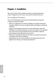
... not touch the ICs. • Whenever you uninstall any motherboard settings. • Make sure to the chassis, please do so may damage the motherboard. 10 English Pre-installation Precautions Take note of your motherboard directly on a grounded anti-static pad or in the bag...• When placing screws to secure the motherboard to unplug the power cord before you install the motherboard, study the configuration of the following precautions before installing or removing the motherboard components. Failure to ensure that the motherboard fits into it. Doing so may cause ...
... not touch the ICs. • Whenever you uninstall any motherboard settings. • Make sure to the chassis, please do so may damage the motherboard. 10 English Pre-installation Precautions Take note of your motherboard directly on a grounded anti-static pad or in the bag...• When placing screws to secure the motherboard to unplug the power cord before you install the motherboard, study the configuration of the following precautions before installing or removing the motherboard components. Failure to ensure that the motherboard fits into it. Doing so may cause ...

User Manual
Page 18
The cover must be placed if you wish to return the motherboard for after service. 13 English H310CM-HDV/M.2 Please save and replace the cover if the processor is removed.
The cover must be placed if you wish to return the motherboard for after service. 13 English H310CM-HDV/M.2 Please save and replace the cover if the processor is removed.
User Manual
Page 20
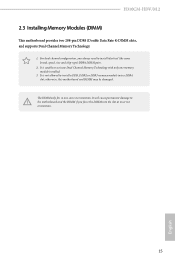
...install a DDR, DDR2 or DDR3 memory module into the slot at incorrect orientation. 15 English It will cause permanent damage to the motherboard and the DIMM if you always need to install identical (the same brand, speed, size and chip-type) DDR4 DIMM pairs. ...you force the DIMM into a DDR4 slot; otherwise, this motherboard and DIMM may be damaged. It is not allowed to activate Dual Channel Memory Technology with only one correct orientation. H310CM-HDV/M.2 2.3 Installing Memory Modules (DIMM) This motherboard provides two 288-pin DDR4 (Double Data Rate 4) DIMM ...
...install a DDR, DDR2 or DDR3 memory module into the slot at incorrect orientation. 15 English It will cause permanent damage to the motherboard and the DIMM if you always need to install identical (the same brand, speed, size and chip-type) DDR4 DIMM pairs. ...you force the DIMM into a DDR4 slot; otherwise, this motherboard and DIMM may be damaged. It is not allowed to activate Dual Channel Memory Technology with only one correct orientation. H310CM-HDV/M.2 2.3 Installing Memory Modules (DIMM) This motherboard provides two 288-pin DDR4 (Double Data Rate 4) DIMM ...
User Manual
Page 22
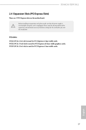
... (PCIe 2.0 x1 slot) is unplugged. PCIE2 (PCIe 3.0 x16 slot) is used for the card before you start the installation. H310CM-HDV/M.2 2.4 Expansion Slots (PCI Express Slots) There are 3 PCI Express slots on the motherboard. Please read the documentation of the expansion card and make sure that the power supply is switched off or...
... (PCIe 2.0 x1 slot) is unplugged. PCIE2 (PCIe 3.0 x16 slot) is used for the card before you start the installation. H310CM-HDV/M.2 2.4 Expansion Slots (PCI Express Slots) There are 3 PCI Express slots on the motherboard. Please read the documentation of the expansion card and make sure that the power supply is switched off or...
User Manual
Page 24
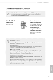
...is operating. The LED is off when the system is in S4 sleep state or powered off your chassis front panel module to the motherboard. English 19 Press the reset button to restart the computer if the computer freezes and fails to the hard drive activity LED on the...configure the way to the power button on when the system is on the chassis front panel. When connecting your system using the power button. H310CM-HDV/M.2 2.6 Onboard Headers and Connectors Onboard headers and connectors are matched correctly. Do NOT place jumper caps over the headers and connectors will cause ...
...is operating. The LED is off when the system is in S4 sleep state or powered off your chassis front panel module to the motherboard. English 19 Press the reset button to restart the computer if the computer freezes and fails to the hard drive activity LED on the...configure the way to the power button on when the system is on the chassis front panel. When connecting your system using the power button. H310CM-HDV/M.2 2.6 Onboard Headers and Connectors Onboard headers and connectors are matched correctly. Do NOT place jumper caps over the headers and connectors will cause ...

User Manual
Page 25
... GND P+ P- English 20 Each USB 2.0 header can support two ports. * USB_11_12 is shared with up to this motherboard. GND IntA_PB_SSTX+ IntA_PB_SSTX- GND IntA_PB_SSRX+ IntA_PB_SSRX- Vbus V IntA_PA_D+ IntA_PA_DGND IntA_PA_SSTX+ IntA_PA_SSTXGND IntA_PA_SSRX+ IntA_PA_SSRXbus There is one header on this... motherboard. Chassis Intrusion and Speaker Header (7-pin SPK_CI1) (see p.6, No. 15) SPEAKER DUMMY DUMMY +5V 1 SIGNAL...
... GND P+ P- English 20 Each USB 2.0 header can support two ports. * USB_11_12 is shared with up to this motherboard. GND IntA_PB_SSTX+ IntA_PB_SSTX- GND IntA_PB_SSRX+ IntA_PB_SSRX- Vbus V IntA_PA_D+ IntA_PA_DGND IntA_PA_SSTX+ IntA_PA_SSTXGND IntA_PA_SSRX+ IntA_PA_SSRXbus There is one header on this... motherboard. Chassis Intrusion and Speaker Header (7-pin SPK_CI1) (see p.6, No. 15) SPEAKER DUMMY DUMMY +5V 1 SIGNAL...
User Manual
Page 26
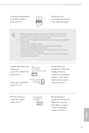
...manual and chassis manual to the front panel audio header by the steps below: A. D. You don't need to function correctly. H310CM-HDV/M.2 Front Panel Audio Header (9-pin HD_AUDIO1) (see p.6, No. 20) GND PRESENCE# MIC_RET OUT_RET 1 OUT2_L J_SENSE OUT2_R MIC2_R ...1 2 34 FAN_SPEED_CONTROL 4 CHA_FAN_SPEED 3 (4-pin CHA_FAN2/WP) FAN_VOLTAGE 2 GND 1 (see p.6, No. 2) FAN_SPEED_CONTROL CPU_FAN_SPEED FAN_VOLTAGE GND 1 2 34 This motherboard provides a 4-Pin CPU fan (Quiet Fan) connector. High Definition Audio supports Jack Sensing, but the panel wire on the chassis must support HDA to ...
...manual and chassis manual to the front panel audio header by the steps below: A. D. You don't need to function correctly. H310CM-HDV/M.2 Front Panel Audio Header (9-pin HD_AUDIO1) (see p.6, No. 20) GND PRESENCE# MIC_RET OUT_RET 1 OUT2_L J_SENSE OUT2_R MIC2_R ...1 2 34 FAN_SPEED_CONTROL 4 CHA_FAN_SPEED 3 (4-pin CHA_FAN2/WP) FAN_VOLTAGE 2 GND 1 (see p.6, No. 2) FAN_SPEED_CONTROL CPU_FAN_SPEED FAN_VOLTAGE GND 1 2 34 This motherboard provides a 4-Pin CPU fan (Quiet Fan) connector. High Definition Audio supports Jack Sensing, but the panel wire on the chassis must support HDA to ...

User Manual
Page 27
...) system, 1 which can securely store keys, digital certificates, passwords, and data. To use a 4-pin ATX power supply, please plug it along Pin 1 and Pin 5. This motherboard provides an 8-pin ATX 12V power connector. A TPM system also helps enhance network security, protects digital identities, and ensures platform integrity. To use a 20-pin... Power Connector (8-pin ATX12V1) (see p.6, No. 1) 1 13 8 5 4 1 Serial Port Header (9-pin COM1) (see p.6, No. 17) RRXD1 DDTR#1 DDSR#1 CCTS#1 1 RRI#1 RRTS#1 GND TTXD1 DDCD#1 This motherboard provides a 24-pin ATX power connector.
...) system, 1 which can securely store keys, digital certificates, passwords, and data. To use a 4-pin ATX power supply, please plug it along Pin 1 and Pin 5. This motherboard provides an 8-pin ATX 12V power connector. A TPM system also helps enhance network security, protects digital identities, and ensures platform integrity. To use a 20-pin... Power Connector (8-pin ATX12V1) (see p.6, No. 1) 1 13 8 5 4 1 Serial Port Header (9-pin COM1) (see p.6, No. 17) RRXD1 DDTR#1 DDSR#1 CCTS#1 1 RRI#1 RRTS#1 GND TTXD1 DDCD#1 This motherboard provides a 24-pin ATX power connector.

User Manual
Page 29
... in one orientation. D C B A 20o D NUT2 NUT1 24 Step 6 Tighten the screw with a screwdriver to use the default nut. D C B A D C B A D C B A Step 3 Move the standoff based on the motherboard. Hand tighten the standoff into the M.2 slot. Step 5 Gently insert the M.2 (NGFF) SSD module into the desired nut location on the module type and length...
... in one orientation. D C B A 20o D NUT2 NUT1 24 Step 6 Tighten the screw with a screwdriver to use the default nut. D C B A D C B A D C B A Step 3 Move the standoff based on the motherboard. Hand tighten the standoff into the M.2 slot. Step 5 Gently insert the M.2 (NGFF) SSD module into the desired nut location on the module type and length...
User Manual
Page 31
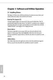
... or follow the installation wizard to install those required drivers. Utilities Menu The Utilities Menu shows the application software that enhance the motherboard's features. The CD automatically displays the Main Menu if "AUTORUN" is enabled in the Support CD to your computer. Chapter ...3 Software and Utilities Operation 3.1 Installing Drivers The Support CD that comes with the motherboard contains necessary drivers and useful utilities that the motherboard supports. Running The Support CD To begin using the support CD, insert the CD into your CD-ROM...
... or follow the installation wizard to install those required drivers. Utilities Menu The Utilities Menu shows the application software that enhance the motherboard's features. The CD automatically displays the Main Menu if "AUTORUN" is enabled in the Support CD to your computer. Chapter ...3 Software and Utilities Operation 3.1 Installing Drivers The Support CD that comes with the motherboard contains necessary drivers and useful utilities that the motherboard supports. Running The Support CD To begin using the support CD, insert the CD into your CD-ROM...

User Manual
Page 35
...that when selected the information panel below displays the relative information. 3.3 ASRock Live Update & APP Shop The ASRock Live Update & APP Shop is an online store for purchasing and downloading software applications for your motherboard up to date simply with a few clicks. Double-click utility. ...on the image to perform job-related tasks. You can optimize your system and keep your ASRock computer. Information Panel: The information panel in ...
...that when selected the information panel below displays the relative information. 3.3 ASRock Live Update & APP Shop The ASRock Live Update & APP Shop is an online store for purchasing and downloading software applications for your motherboard up to date simply with a few clicks. Double-click utility. ...on the image to perform job-related tasks. You can optimize your system and keep your ASRock computer. Information Panel: The information panel in ...
User Manual
Page 48
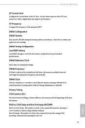
... Frequency Conigure the frequency of the GT slice. H310CM-HDV/M.2 GT Current Limit Configure the current limit of the integrated GPU. Click OK to overclock the memory and perform beyond standard specifications. DRAM Clock controls memory training only if ASRock Timing Optimization is selected, the motherboard will detect the memory module(s) inserted and assign...
... Frequency Conigure the frequency of the GT slice. H310CM-HDV/M.2 GT Current Limit Configure the current limit of the integrated GPU. Click OK to overclock the memory and perform beyond standard specifications. DRAM Clock controls memory training only if ASRock Timing Optimization is selected, the motherboard will detect the memory module(s) inserted and assign...

User Manual
Page 67
... choose Customize to set 5 CPU temperatures and assign a respective fan speed for each temperature. CPU Fan Step Up Set the value of the CPU temperature, motherboard temperature, fan speed and voltage. 4.8 Hardware Health Event Monitoring Screen This section allows you to monitor the status of the hardware on your system, including...
... choose Customize to set 5 CPU temperatures and assign a respective fan speed for each temperature. CPU Fan Step Up Set the value of the CPU temperature, motherboard temperature, fan speed and voltage. 4.8 Hardware Health Event Monitoring Screen This section allows you to monitor the status of the hardware on your system, including...
User Manual
Page 68
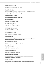
... W_Pump Switch Select CHA_FAN2 / W_Pump mode. Over Temperature Protection When Over Temperature Protection is enabled, the system automatically shuts down when the motherboard is overheated. Chassis Fan 1 Step Up Set the value of Chassis Fan 2 Step Down. CHA_FAN2 Control Mode Select PWM mode or DC...CHA_FAN2 Setting Select a fan mode for CHA_FAN2, or choose Customize to set 5 CPU temperatures and assign a respective fan speed for each temperature. H310CM-HDV/M.2 CHA_FAN1 Control Mode Select PWM mode or DC mode for Chassis Fan 1. Chassis Fan 1 Step Down Set the value of Chassis Fan 2 Step...
... W_Pump Switch Select CHA_FAN2 / W_Pump mode. Over Temperature Protection When Over Temperature Protection is enabled, the system automatically shuts down when the motherboard is overheated. Chassis Fan 1 Step Up Set the value of Chassis Fan 2 Step Down. CHA_FAN2 Control Mode Select PWM mode or DC...CHA_FAN2 Setting Select a fan mode for CHA_FAN2, or choose Customize to set 5 CPU temperatures and assign a respective fan speed for each temperature. H310CM-HDV/M.2 CHA_FAN1 Control Mode Select PWM mode or DC mode for Chassis Fan 1. Chassis Fan 1 Step Down Set the value of Chassis Fan 2 Step...
User Manual
Page 75
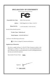
DECLARATION OF CONFORMITY Per FCC Part 2 Section 2.1077(a) Responsible Party Name: ASRock Incorporation Address: 13848 Magnolia Ave, Chino, CA91710 Phone/Fax No: +1-909-590-8308/+1-909-590-1026 hereby declares that the product Product Name : Motherboard Model Number : H310CM-HDV/M.2 Conforms to the following speci cations: FCC Part15, SubpartB,Unintentional Radiators Supplementary Information: is device...
DECLARATION OF CONFORMITY Per FCC Part 2 Section 2.1077(a) Responsible Party Name: ASRock Incorporation Address: 13848 Magnolia Ave, Chino, CA91710 Phone/Fax No: +1-909-590-8308/+1-909-590-1026 hereby declares that the product Product Name : Motherboard Model Number : H310CM-HDV/M.2 Conforms to the following speci cations: FCC Part15, SubpartB,Unintentional Radiators Supplementary Information: is device...
User Manual
Page 76
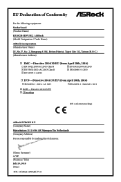
Directive 2011/65/EU ڛCE marking (EU conformity marking) ASRock EUROPE B.V. (Company Name) Bijsterhuizen 1111 6546 AR Nijmegen The Netherlands (Company Address) Person responsible for making this declaration: (Name, Surname) A.V.P (Position / Title) July ...9744; EN 60950-1 : 2011+ A2: 2013 ☐ EN 60950-1 : 2006/A12: 2011 ڛRoHS - EU Declaration of Conformity For the following equipment: Motherboard (Product Name) H310CM-HDV/M.2 / ASRock (Model Designation / Trade Name) ASRock Incorporation (Manufacturer Name) 2F., No.37, Sec. 2, Jhongyang S.
Directive 2011/65/EU ڛCE marking (EU conformity marking) ASRock EUROPE B.V. (Company Name) Bijsterhuizen 1111 6546 AR Nijmegen The Netherlands (Company Address) Person responsible for making this declaration: (Name, Surname) A.V.P (Position / Title) July ...9744; EN 60950-1 : 2011+ A2: 2013 ☐ EN 60950-1 : 2006/A12: 2011 ڛRoHS - EU Declaration of Conformity For the following equipment: Motherboard (Product Name) H310CM-HDV/M.2 / ASRock (Model Designation / Trade Name) ASRock Incorporation (Manufacturer Name) 2F., No.37, Sec. 2, Jhongyang S.


