
User Manual
Page 2
..., please follow the related regulations in Perchlorate Best Management Practices (BMP) regulations passed by ASRock. Version 1.0 Published January 2017 Copyright©2017 ASRock INC. ASRock assumes no event shall ASRock, its directors, officers, employees, or agents be reproduced, transcribed, transmitted, or translated...interruption of business and the like), even if ASRock has been advised of the possibility of such damages arising from any means, except duplication of the FCC Rules. Copyright Notice: No part of this motherboard contains Perchlorate, a toxic substance controlled in ...
..., please follow the related regulations in Perchlorate Best Management Practices (BMP) regulations passed by ASRock. Version 1.0 Published January 2017 Copyright©2017 ASRock INC. ASRock assumes no event shall ASRock, its directors, officers, employees, or agents be reproduced, transcribed, transmitted, or translated...interruption of business and the like), even if ASRock has been advised of the possibility of such damages arising from any means, except duplication of the FCC Rules. Copyright Notice: No part of this motherboard contains Perchlorate, a toxic substance controlled in ...
User Manual
Page 6
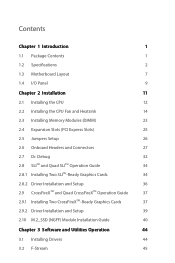
Contents Chapter 1 Introduction 1 1.1 Package Contents 1 1.2 Specifications 2 1.3 Motherboard Layout 7 1.4 I/O Panel 9 Chapter 2 Installation 11 2.1 Installing the CPU 12 2.2 Installing the CPU Fan and Heatsink 14 2.3 Installing Memory Modules (DIMM) 23 2.4 Expansion Slots (PCI Express ...
Contents Chapter 1 Introduction 1 1.1 Package Contents 1 1.2 Specifications 2 1.3 Motherboard Layout 7 1.4 I/O Panel 9 Chapter 2 Installation 11 2.1 Installing the CPU 12 2.2 Installing the CPU Fan and Heatsink 14 2.3 Installing Memory Modules (DIMM) 23 2.4 Expansion Slots (PCI Express ...

User Manual
Page 9
... to quality and endurance. ASRock website http://www.asrock.com. 1.1 Package Contents • ASRock Fatal1ty X370 Gaming K4 Series Motherboard (ATX Form Factor) • ASRock Fatal1ty X370 Gaming K4 Series Quick Installation Guide • ASRock Fatal1ty X370 Gaming K4 Series Support CD • 1 x I/O Panel Shield • 4 x Serial ATA (SATA) Data Cables (Optional) • 1 x ASRock SLI_HB_Bridge_2S Card (Optional) • 3 x Screws for purchasing ASRock Fatal1ty X370 Gaming K4 Series motherboard, a reliable motherboard produced under ASRock's consistently stringent quality control...
... to quality and endurance. ASRock website http://www.asrock.com. 1.1 Package Contents • ASRock Fatal1ty X370 Gaming K4 Series Motherboard (ATX Form Factor) • ASRock Fatal1ty X370 Gaming K4 Series Quick Installation Guide • ASRock Fatal1ty X370 Gaming K4 Series Support CD • 1 x I/O Panel Shield • 4 x Serial ATA (SATA) Data Cables (Optional) • 1 x ASRock SLI_HB_Bridge_2S Card (Optional) • 3 x Screws for purchasing ASRock Fatal1ty X370 Gaming K4 Series motherboard, a reliable motherboard produced under ASRock's consistently stringent quality control...
User Manual
Page 15
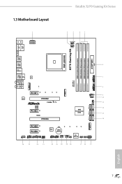
1.3 Motherboard Layout Fatal1ty X370 Gaming K4 Series Bottom: Optical SPDIF 1 2 3 45 CPU_OPT/W_PUMP CPU_FAN1 PS2 Mouse PS2 Keyboard X370 Gaming K4 HDMI1 SOCKET AM4 USB 3.0 T: USB1 B: USB2 USB 3.0 T: USB3 B: USB4 USB 3.1 T: USB3_TA_1 B: USB3_TC_1 USB 3.0 T: USB5 ...) DDR4_B2 (64 bit, 288-pin module) 6 7 USB3_9_10 1 1 USB_5 1 AMD_FAN_LED1 1 USB3_7_8 8 9 10 CHA_FAN1 11 SATA3_5_6 12 AMD Promontory X370 13 SATA3_3_4 14 ATXPWR1 SATA3_1_2 M2_2 PCIE5 PCIE6 HD_AUDIO1 COM1 1 1 1 TPMS1 SPK_PLED1 1 26 25 24 23 Super I/O CMOS Battery USB_3_4 USB_1_2 1 ...
1.3 Motherboard Layout Fatal1ty X370 Gaming K4 Series Bottom: Optical SPDIF 1 2 3 45 CPU_OPT/W_PUMP CPU_FAN1 PS2 Mouse PS2 Keyboard X370 Gaming K4 HDMI1 SOCKET AM4 USB 3.0 T: USB1 B: USB2 USB 3.0 T: USB3 B: USB4 USB 3.1 T: USB3_TA_1 B: USB3_TC_1 USB 3.0 T: USB5 ...) DDR4_B2 (64 bit, 288-pin module) 6 7 USB3_9_10 1 1 USB_5 1 AMD_FAN_LED1 1 USB3_7_8 8 9 10 CHA_FAN1 11 SATA3_5_6 12 AMD Promontory X370 13 SATA3_3_4 14 ATXPWR1 SATA3_1_2 M2_2 PCIE5 PCIE6 HD_AUDIO1 COM1 1 1 1 TPMS1 SPK_PLED1 1 26 25 24 23 Super I/O CMOS Battery USB_3_4 USB_1_2 1 ...
User Manual
Page 19
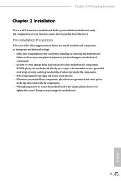
... place them on a carpet. Doing so may cause physical injuries to you and damages to motherboard components. • In order to avoid damage from static electricity to the motherboard's components, NEVER place your chassis to ensure that comes with the components. • When ...of your motherboard directly on a grounded anti-static pad or in the bag that the motherboard fits into it. Also remember to do not overtighten the screws! Failure to use a grounded wrist strap or touch a safety grounded object before installing or removing the motherboard. Fatal1ty X370 Gaming K4 Series ...
... place them on a carpet. Doing so may cause physical injuries to you and damages to motherboard components. • In order to avoid damage from static electricity to the motherboard's components, NEVER place your chassis to ensure that comes with the components. • When ...of your motherboard directly on a grounded anti-static pad or in the bag that the motherboard fits into it. Also remember to do not overtighten the screws! Failure to use a grounded wrist strap or touch a safety grounded object before installing or removing the motherboard. Fatal1ty X370 Gaming K4 Series ...

User Manual
Page 22
2.2 Installing the CPU Fan and Heatsink After you install the CPU into this motherboard, it is necessary to install a larger heatsink and cooling fan to improve heat dissipation. Make sure that the CPU and the heatsink are securely fastened and in good contact with each other. Installing the CPU Box Cooler SR1 1 2 14 English Please turn off the power or remove the power cord before changing a CPU or heatsink. You also need to spray thermal grease between the CPU and the heatsink to dissipate heat.
2.2 Installing the CPU Fan and Heatsink After you install the CPU into this motherboard, it is necessary to install a larger heatsink and cooling fan to improve heat dissipation. Make sure that the CPU and the heatsink are securely fastened and in good contact with each other. Installing the CPU Box Cooler SR1 1 2 14 English Please turn off the power or remove the power cord before changing a CPU or heatsink. You also need to spray thermal grease between the CPU and the heatsink to dissipate heat.
User Manual
Page 31
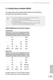
...: Single rank DIMM, 1Rx4 or 1Rx8 on DIMM module label DR: Dual rank DIMM, 2Rx4 or 2Rx8 on DIMM module label 23 English SR - Fatal1ty X370 Gaming K4 Series 2.3 Installing Memory Modules (DIMM) This motherboard provides four 288-pin DDR4 (Double Data Rate 4) DIMM slots, and supports Dual Channel Memory Technology. 1. SR - DR - - - SR - - 2667...
...: Single rank DIMM, 1Rx4 or 1Rx8 on DIMM module label DR: Dual rank DIMM, 2Rx4 or 2Rx8 on DIMM module label 23 English SR - Fatal1ty X370 Gaming K4 Series 2.3 Installing Memory Modules (DIMM) This motherboard provides four 288-pin DDR4 (Double Data Rate 4) DIMM slots, and supports Dual Channel Memory Technology. 1. SR - DR - - - SR - - 2667...

User Manual
Page 32
The DIMM only fits in one correct orientation. It will cause permanent damage to the motherboard and the DIMM if you force the DIMM into the slot at incorrect orientation. 1 2 3 24 English
The DIMM only fits in one correct orientation. It will cause permanent damage to the motherboard and the DIMM if you force the DIMM into the slot at incorrect orientation. 1 2 3 24 English

User Manual
Page 33
Fatal1ty X370 Gaming K4 Series 2.4 Expansion Slots (PCI Express Slots) There are 6 PCI Express slots on the motherboard. PCIE4 (PCIe 3.0 x16 slot) is used for PCI Express x8 lane width graphics cards. PCIe Slot Configurations 7th A-Series APUs : Single Graphics Card...Two Graphics Cards in CrossFireXTM or SLITM Mode PCIE2 x16 x8 PCIE4 N/A x8 English For a better thermal environment, please connect a chassis fan to the motherboard's chassis fan connector (CHA_FAN1 or CHA_FAN2) when using multiple graphics cards. 25 PCIE2 (PCIe 3.0 x16 slot) is used for PCI Express x1 lane width...
Fatal1ty X370 Gaming K4 Series 2.4 Expansion Slots (PCI Express Slots) There are 6 PCI Express slots on the motherboard. PCIE4 (PCIe 3.0 x16 slot) is used for PCI Express x8 lane width graphics cards. PCIe Slot Configurations 7th A-Series APUs : Single Graphics Card...Two Graphics Cards in CrossFireXTM or SLITM Mode PCIE2 x16 x8 PCIE4 N/A x8 English For a better thermal environment, please connect a chassis fan to the motherboard's chassis fan connector (CHA_FAN1 or CHA_FAN2) when using multiple graphics cards. 25 PCIE2 (PCIe 3.0 x16 slot) is used for PCI Express x1 lane width...

User Manual
Page 35
... indicator on when the hard drive is on the chassis front panel. The front panel design may configure the way to the motherboard. Note the positive and negative pins before connecting the cables. The LED keeps blinking when the system is in S1/S3 sleep...when the system is in S4 sleep state or powered off (S5). You may differ by chassis. When connecting your system using the power switch. Fatal1ty X370 Gaming K4 Series 2.6 Onboard Headers and Connectors Onboard headers and connectors are matched correctly. System Panel Header (9-pin PANEL1) (see p.7, No. 15) PLED+...
... indicator on when the hard drive is on the chassis front panel. The front panel design may configure the way to the motherboard. Note the positive and negative pins before connecting the cables. The LED keeps blinking when the system is in S1/S3 sleep...when the system is in S4 sleep state or powered off (S5). You may differ by chassis. When connecting your system using the power switch. Fatal1ty X370 Gaming K4 Series 2.6 Onboard Headers and Connectors Onboard headers and connectors are matched correctly. System Panel Header (9-pin PANEL1) (see p.7, No. 15) PLED+...

User Manual
Page 36
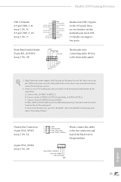
... on this header. Each USB 2.0 header can support two ports. 28 English P+ USB_PWR This header is used for internal storage devices with up to this motherboard. USB 2.0 Headers ((9-pin USB_1_2) (see p.7, No. 21) (9-pin USB_3_4) (see p.7, No. 22) USB_PWR PP+ GND DUMMY 1 GND P+ PUSB_PWR There are two headers on the AMD...
... on this header. Each USB 2.0 header can support two ports. 28 English P+ USB_PWR This header is used for internal storage devices with up to this motherboard. USB 2.0 Headers ((9-pin USB_1_2) (see p.7, No. 21) (9-pin USB_3_4) (see p.7, No. 22) USB_PWR PP+ GND DUMMY 1 GND P+ PUSB_PWR There are two headers on the AMD...
User Manual
Page 37
... follow the instructions in the Realtek Control panel and adjust "Recording Volume". Connect Mic_IN (MIC) to Ground (GND). Each USB 3.0 header can support two ports. Fatal1ty X370 Gaming K4 Series USB 3.0 Header (19-pin USB3_7_8) (see p.7, No. 8) (19-pin USB3_9_10) (see p.7, No. 7) Vbus IntA_PA_SSRXIntA_PA_SSRX+ GND IntA_PA_SSTXIntA_PA_SSTX+ GND IntA_PA_DIntA_PA_D+ Vbus IntA_PB_SSRXIntA_PB_SSRX+ GND ... FAN_SPEED_CONTROL match the black wire to the front audio panel. 1. C. Connect Ground (GND) to MIC2_L. MIC_RET and OUT_RET are two headers on this motherboard. E.
... follow the instructions in the Realtek Control panel and adjust "Recording Volume". Connect Mic_IN (MIC) to Ground (GND). Each USB 3.0 header can support two ports. Fatal1ty X370 Gaming K4 Series USB 3.0 Header (19-pin USB3_7_8) (see p.7, No. 8) (19-pin USB3_9_10) (see p.7, No. 7) Vbus IntA_PA_SSRXIntA_PA_SSRX+ GND IntA_PA_SSTXIntA_PA_SSTX+ GND IntA_PA_DIntA_PA_D+ Vbus IntA_PB_SSRXIntA_PB_SSRX+ GND ... FAN_SPEED_CONTROL match the black wire to the front audio panel. 1. C. Connect Ground (GND) to MIC2_L. MIC_RET and OUT_RET are two headers on this motherboard. E.

User Manual
Page 38
...along Pin 1 and Pin 13. CPU Fan Connectors (4-pin CPU_FAN1) (see p.7, No. 3) FAN_SPEED_CONTROL CPU_FAN_SPEED FAN_VOLTAGE GND 1 2 34 This motherboard provides a 4-Pin water cooling CPU fan connector. If you plan to connect a 3-Pin CPU fan, please connect it to Pin 1-3....to Pin 1-3. CPU Optional/Water Pump Fan Connector (4-pin CPU_OPT/W_ PUMP) (see p.7, No. 2) FAN_SPEED_CONTROL CPU_FAN_SPEED FAN_VOLTAGE GND 1 2 34 This motherboard provides a 4-Pin CPU fan (Quiet Fan) connector. English 30 Chassis Optional/Water Pump Fan Connector (4-pin CHA_FAN3/W_ PUMP) (see p.7, No...
...along Pin 1 and Pin 13. CPU Fan Connectors (4-pin CPU_FAN1) (see p.7, No. 3) FAN_SPEED_CONTROL CPU_FAN_SPEED FAN_VOLTAGE GND 1 2 34 This motherboard provides a 4-Pin water cooling CPU fan connector. If you plan to connect a 3-Pin CPU fan, please connect it to Pin 1-3....to Pin 1-3. CPU Optional/Water Pump Fan Connector (4-pin CPU_OPT/W_ PUMP) (see p.7, No. 2) FAN_SPEED_CONTROL CPU_FAN_SPEED FAN_VOLTAGE GND 1 2 34 This motherboard provides a 4-Pin CPU fan (Quiet Fan) connector. English 30 Chassis Optional/Water Pump Fan Connector (4-pin CHA_FAN3/W_ PUMP) (see p.7, No...

User Manual
Page 42
... recommended to two identical PCI Express x16 graphics cards. Make sure that the cards are NVIDIA® certified. 2. 2.8 SLITM and Quad SLITM Operation Guide This motherboard supports NVIDIA® SLITM and Quad SLITM (Scalable Link Interface) technology that allows you to install up to use identical SLITM-ready graphics cards that...
... recommended to two identical PCI Express x16 graphics cards. Make sure that the cards are NVIDIA® certified. 2. 2.8 SLITM and Quad SLITM Operation Guide This motherboard supports NVIDIA® SLITM and Quad SLITM (Scalable Link Interface) technology that allows you to install up to use identical SLITM-ready graphics cards that...
User Manual
Page 45
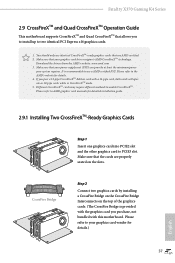
Fatal1ty X370 Gaming K4 Series 2.9 CrossFireXTM and Quad CrossFireXTM Operation Guide This motherboard supports CrossFireXTM and Quad CrossFireXTM that your graphics card driver supports AMD CrossFireXTM technology. Make sure that allows you to install up to ... to two identical PCI Express x16 graphics cards. 1. It is provided with the graphics card you pair a 12-pipe CrossFireXTM Edition card with this motherboard. Please refer to AMD graphics card manuals for detailed installation guide. 2.9.1 Installing Two CrossFireXTM-Ready Graphics Cards Step 1 Insert one graphics card into PCIE2...
Fatal1ty X370 Gaming K4 Series 2.9 CrossFireXTM and Quad CrossFireXTM Operation Guide This motherboard supports CrossFireXTM and Quad CrossFireXTM that your graphics card driver supports AMD CrossFireXTM technology. Make sure that allows you to install up to ... to two identical PCI Express x16 graphics cards. 1. It is provided with the graphics card you pair a 12-pipe CrossFireXTM Edition card with this motherboard. Please refer to AMD graphics card manuals for detailed installation guide. 2.9.1 Installing Two CrossFireXTM-Ready Graphics Cards Step 1 Insert one graphics card into PCIE2...

User Manual
Page 49
Otherwise, release the standoff by default. Please be used. D C B A D C B A D C B A C B A D NUT2 NUT1 Fatal1ty X370 Gaming K4 Series Step 3 Move the standoff based on the motherboard. The standoff is placed at the nut location D by hand. Please do not overtighten the screw as this might damage the module. 41 English Step 5 ...
Otherwise, release the standoff by default. Please be used. D C B A D C B A D C B A C B A D NUT2 NUT1 Fatal1ty X370 Gaming K4 Series Step 3 Move the standoff based on the motherboard. The standoff is placed at the nut location D by hand. Please do not overtighten the screw as this might damage the module. 41 English Step 5 ...

User Manual
Page 52
... work properly. Chapter 3 Software and Utilities Operation 3.1 Installing Drivers The Support CD that comes with the motherboard contains necessary drivers and useful utilities that the motherboard supports. Drivers Menu The drivers compatible to install it. To improve Windows 7 compatibility, please download and install...support CD, insert the CD into your computer. Utilities Menu The Utilities Menu shows the application software that enhance the motherboard's features. Click on the file "ASRSETUP.EXE" in your CD-ROM drive. "KB2720599": http://support.microsoft.com/kb/2720599...
... work properly. Chapter 3 Software and Utilities Operation 3.1 Installing Drivers The Support CD that comes with the motherboard contains necessary drivers and useful utilities that the motherboard supports. Drivers Menu The drivers compatible to install it. To improve Windows 7 compatibility, please download and install...support CD, insert the CD into your computer. Utilities Menu The Utilities Menu shows the application software that enhance the motherboard's features. Click on the file "ASRSETUP.EXE" in your CD-ROM drive. "KB2720599": http://support.microsoft.com/kb/2720599...

User Manual
Page 56
... the selected news and know more. 48 English Click on your desktop to access ASRock Live Update & APP Shop *You need to be connected to the Internet to download apps from the ASRock Live Update & APP Shop. 3.3.1 UI Overview Category Panel Hot News Information Panel ... the various latest news. Double-click utility. You can optimize your system and keep your ASRock computer. 3.3 ASRock Live Update & APP Shop The ASRock Live Update & APP Shop is an online store for purchasing and downloading software applications for your motherboard up to date simply with a few clicks.
... the selected news and know more. 48 English Click on your desktop to access ASRock Live Update & APP Shop *You need to be connected to the Internet to download apps from the ASRock Live Update & APP Shop. 3.3.1 UI Overview Category Panel Hot News Information Panel ... the various latest news. Double-click utility. You can optimize your system and keep your ASRock computer. 3.3 ASRock Live Update & APP Shop The ASRock Live Update & APP Shop is an online store for purchasing and downloading software applications for your motherboard up to date simply with a few clicks.

User Manual
Page 63
...RGB LED strips do so may be damaged. 2. The RGB LED header supports standard 5050 RGB LED strip (12V/G/R/B), with sophisticated tastes to motherboard components. 1. X370 Gaming K4 English 1 FATAL TY 1 B 12V G R RGB_LED2 1 12V G R B RGB_LED1 1 12V G R B 1. Before installing or ... and more. Fatal1ty X370 Gaming K4 Series 3.5 ASRock RGB LED ASRock RGB LED is a lighting control utility specifically designed for unique individuals with a maximum power rating of 3A (12V) and length within 2 meters. 55 Failure to the RGB LED Headers (RGB_LED1, RGB_LED2) on the motherboard.
...RGB LED strips do so may be damaged. 2. The RGB LED header supports standard 5050 RGB LED strip (12V/G/R/B), with sophisticated tastes to motherboard components. 1. X370 Gaming K4 English 1 FATAL TY 1 B 12V G R RGB_LED2 1 12V G R B RGB_LED1 1 12V G R B 1. Before installing or ... and more. Fatal1ty X370 Gaming K4 Series 3.5 ASRock RGB LED ASRock RGB LED is a lighting control utility specifically designed for unique individuals with a maximum power rating of 3A (12V) and length within 2 meters. 55 Failure to the RGB LED Headers (RGB_LED1, RGB_LED2) on the motherboard.

User Manual
Page 64
Toggle on/off the RGB LED switch Sync RGB LED effects for all LED regions of the motherboard Select a RGB LED light effect from the ASRock Live Update & APP Shop and start coloring your PC style your preference. Download this utility from the drop-down menu. ASRock RGB LED Utility Now you can adjust the RGB LED color through the ASRock RGB LED utility. English 56 Drag the tab to customize your way!
Toggle on/off the RGB LED switch Sync RGB LED effects for all LED regions of the motherboard Select a RGB LED light effect from the ASRock Live Update & APP Shop and start coloring your PC style your preference. Download this utility from the drop-down menu. ASRock RGB LED Utility Now you can adjust the RGB LED color through the ASRock RGB LED utility. English 56 Drag the tab to customize your way!


