
User Manual
Page 6
... support related to change without further notice. Chapter 4 contains the coniguration guide of the sotware and utilities. ASRock website http://www.asrock.com. 1.1 Package Contents • ASRock B150M-ITX/D3 Motherboard (Mini-ITX Form Factor) • ASRock B150M-ITX/D3 Quick Installation Guide • ASRock B150M-ITX/D3 Support CD • 2 x Serial ATA (SATA) Data Cables (Optional) • 1 x I/O Panel Shield • 1 x WiFi Module Bracket •...
... support related to change without further notice. Chapter 4 contains the coniguration guide of the sotware and utilities. ASRock website http://www.asrock.com. 1.1 Package Contents • ASRock B150M-ITX/D3 Motherboard (Mini-ITX Form Factor) • ASRock B150M-ITX/D3 Quick Installation Guide • ASRock B150M-ITX/D3 Support CD • 2 x Serial ATA (SATA) Data Cables (Optional) • 1 x I/O Panel Shield • 1 x WiFi Module Bracket •...
User Manual
Page 8
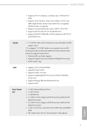
...; Gigabit LAN 10/100/1000 Mb/s • Giga PHY Intel® I219V • Supports Wake-On-LAN • Supports Lightning/ESD Protection (ASRock Full Spike Protection) • Supports Energy Eicient Ethernet 802.3az • Supports PXE Rear Panel I/O • 1 x PS/2 Mouse/Keyboard Port...8226; 1 x HDMI Port • 2 x USB 2.0 Ports (Supports ESD Protection (ASRock Full Spike Protection)) • 4 x USB 3.0 Ports (Supports ESD Protection (ASRock Full Spike Protection)) • 1 x RJ-45 LAN Port with max. B150M-ITX/D3 • Supports DVI-D with LED (ACT/LINK LED and SPEED LED) • ...
...; Gigabit LAN 10/100/1000 Mb/s • Giga PHY Intel® I219V • Supports Wake-On-LAN • Supports Lightning/ESD Protection (ASRock Full Spike Protection) • Supports Energy Eicient Ethernet 802.3az • Supports PXE Rear Panel I/O • 1 x PS/2 Mouse/Keyboard Port...8226; 1 x HDMI Port • 2 x USB 2.0 Ports (Supports ESD Protection (ASRock Full Spike Protection)) • 4 x USB 3.0 Ports (Supports ESD Protection (ASRock Full Spike Protection)) • 1 x RJ-45 LAN Port with max. B150M-ITX/D3 • Supports DVI-D with LED (ACT/LINK LED and SPEED LED) • ...
User Manual
Page 10
B150M-ITX/D3 Certiications • FCC, CE, WHQL • ErP/EuP Ready (ErP/EuP ready power supply is required) * For detailed product information, please visit our website: http://www.asrock.com Please realize that there is a certain risk involved with overclocking, including adjusting the setting in the BIOS, applying Untied Overclocking Technology, or using third...
B150M-ITX/D3 Certiications • FCC, CE, WHQL • ErP/EuP Ready (ErP/EuP ready power supply is required) * For detailed product information, please visit our website: http://www.asrock.com Please realize that there is a certain risk involved with overclocking, including adjusting the setting in the BIOS, applying Untied Overclocking Technology, or using third...
User Manual
Page 11
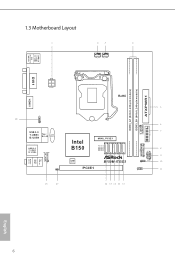
1.3 Motherboard Layout CHA_FAN1 CPU_FAN1 USB 2.0 T: USB1 B: USB2 PS2 Keyboard /Mouse DVI1 HDMI1 AT X P W R 1 DDR3_A1 (64 bit, 240-pin module) DDR3_B1 (64 bit, 240-pin module) ATX12V1 RoHS USB11 1 USB 3.0 T: USB3 B: USB4 Top: RJ-45 CMOS Battery USB 3.0 T: USB5 B: USB6 HD_AUDIO1 1 CI1 1 Intel B150 SATA3_4 SATA3_3 SATA3_2 SATA3_1 SATA3_0 MINI_PCIE1 128Mb BIOS PCIE1 B150M-ITX/D3 1 USB_9_10 1 SPEAKER1 1 1 PANEL1 CLRMOS1 1 Top: LINE IN Center: FRONT Bottom: MIC IN USB3_7_8 TPMS1 PLED PWRBTN HDLED RESET English 6
1.3 Motherboard Layout CHA_FAN1 CPU_FAN1 USB 2.0 T: USB1 B: USB2 PS2 Keyboard /Mouse DVI1 HDMI1 AT X P W R 1 DDR3_A1 (64 bit, 240-pin module) DDR3_B1 (64 bit, 240-pin module) ATX12V1 RoHS USB11 1 USB 3.0 T: USB3 B: USB4 Top: RJ-45 CMOS Battery USB 3.0 T: USB5 B: USB6 HD_AUDIO1 1 CI1 1 Intel B150 SATA3_4 SATA3_3 SATA3_2 SATA3_1 SATA3_0 MINI_PCIE1 128Mb BIOS PCIE1 B150M-ITX/D3 1 USB_9_10 1 SPEAKER1 1 1 PANEL1 CLRMOS1 1 Top: LINE IN Center: FRONT Bottom: MIC IN USB3_7_8 TPMS1 PLED PWRBTN HDLED RESET English 6

User Manual
Page 14
Function of the Audio Ports in the Realtek HD Audio Manager. Please set Speaker Coniguration to use an HD front panel audio module and enable the multichannel audio feature through the audio driver. B150M-ITX/D3 ** To conigure 7.1 CH HD Audio, it is required to "7.1 Speaker"in 7.1-channel Coniguration: Port Light Blue (Rear panel) Lime (Rear panel) Pink (Rear panel) Lime (Front panel) Function Rear Speaker Out Front Speaker Out Central /Subwoofer Speaker Out Side Speaker Out 9 English
Function of the Audio Ports in the Realtek HD Audio Manager. Please set Speaker Coniguration to use an HD front panel audio module and enable the multichannel audio feature through the audio driver. B150M-ITX/D3 ** To conigure 7.1 CH HD Audio, it is required to "7.1 Speaker"in 7.1-channel Coniguration: Port Light Blue (Rear panel) Lime (Rear panel) Pink (Rear panel) Lime (Front panel) Function Rear Speaker Out Front Speaker Out Central /Subwoofer Speaker Out Side Speaker Out 9 English

User Manual
Page 16
Otherwise, the CPU will be seriously damaged. 2. Do not force to insert the CPU into the socket, please check if the PnP cap is on the socket, if the CPU surface is found. Unplug all power cables before installing the CPU. 1 A B 2 11 English Before you insert the 1151-Pin CPU into the socket if above situation is unclean, or if there are any bent pins in the socket. B150M-ITX/D3 2.1 Installing the CPU 1.
Otherwise, the CPU will be seriously damaged. 2. Do not force to insert the CPU into the socket, please check if the PnP cap is on the socket, if the CPU surface is found. Unplug all power cables before installing the CPU. 1 A B 2 11 English Before you insert the 1151-Pin CPU into the socket if above situation is unclean, or if there are any bent pins in the socket. B150M-ITX/D3 2.1 Installing the CPU 1.

User Manual
Page 18
he cover must be placed if you wish to return the motherboard for ater service. 13 English B150M-ITX/D3 Please save and replace the cover if the processor is removed.
he cover must be placed if you wish to return the motherboard for ater service. 13 English B150M-ITX/D3 Please save and replace the cover if the processor is removed.

User Manual
Page 20
... to the motherboard and the DIMM if you always need to install a DDR or DDR2 memory module into the slot at incorrect orientation. 15 English B150M-ITX/D3 2.3 Installing Memory Modules (DIMM) his motherboard provides two 240-pin DDR3/DDR3L (Double Data Rate 3) DIMM slots, and supports Dual Channel Memory Technology. 1. he DIMM...
... to the motherboard and the DIMM if you always need to install a DDR or DDR2 memory module into the slot at incorrect orientation. 15 English B150M-ITX/D3 2.3 Installing Memory Modules (DIMM) his motherboard provides two 240-pin DDR3/DDR3L (Double Data Rate 3) DIMM slots, and supports Dual Channel Memory Technology. 1. he DIMM...

User Manual
Page 22
Before installing an expansion card, please make necessary hardware settings for PCI Express x16 lane width graphics cards. Please read the documentation of the expansion card and make sure that the power supply is switched of or the power cord is used for WiFi and mSATA devices. 17 English PCIe slot: PCIE1 (PCIe 3.0 x16 slot) is unplugged. mini-PCIe slot: MPCIE1 (mini-PCIe slot) is 1 PCI Express slot and 1 mini-PCI Express slot on the motherboard. B150M-ITX/D3 2.4 Expansion Slots (PCI Express Slots) here is used for the card before you start the installation.
Before installing an expansion card, please make necessary hardware settings for PCI Express x16 lane width graphics cards. Please read the documentation of the expansion card and make sure that the power supply is switched of or the power cord is used for WiFi and mSATA devices. 17 English PCIe slot: PCIE1 (PCIe 3.0 x16 slot) is unplugged. mini-PCIe slot: MPCIE1 (mini-PCIe slot) is 1 PCI Express slot and 1 mini-PCI Express slot on the motherboard. B150M-ITX/D3 2.4 Expansion Slots (PCI Express Slots) here is used for the card before you start the installation.

User Manual
Page 24
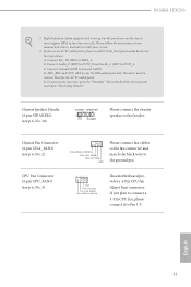
... is on the chassis front panel. Note the positive and negative pins before connecting the cables. PWRBTN (Power Switch): Connect to the pin assignments below. B150M-ITX/D3 2.6 Onboard Headers and Connectors Onboard headers and connectors are matched correctly. Do NOT place jumper caps over the headers and connectors will cause permanent damage...
... is on the chassis front panel. Note the positive and negative pins before connecting the cables. PWRBTN (Power Switch): Connect to the pin assignments below. B150M-ITX/D3 2.6 Onboard Headers and Connectors Onboard headers and connectors are matched correctly. Do NOT place jumper caps over the headers and connectors will cause permanent damage...
User Manual
Page 26
... mic, go to MIC2_L. Connect Mic_IN (MIC) to the "FrontMic" Tab in our manual and chassis manual to OUT2_L. Connect Ground (GND) to function correctly. D. B150M-ITX/D3 1. High Deinition Audio supports Jack Sensing, but the panel wire on the chassis must support HDA to Ground (GND). If you use an AC'97...
... mic, go to MIC2_L. Connect Mic_IN (MIC) to the "FrontMic" Tab in our manual and chassis manual to OUT2_L. Connect Ground (GND) to function correctly. D. B150M-ITX/D3 1. High Deinition Audio supports Jack Sensing, but the panel wire on the chassis must support HDA to Ground (GND). If you use an AC'97...
User Manual
Page 28
... the Main Menu if "AUTORUN" is enabled in the Support CD to install it. "KB2720599": http://support.microsot.com/kb/2720599/en-us 23 English B150M-ITX/D3 Chapter 3 Software and Utilities Operation 3.1 Installing Drivers he Support CD that comes with the motherboard contains necessary drivers and useful utilities that the motherboard supports...
... the Main Menu if "AUTORUN" is enabled in the Support CD to install it. "KB2720599": http://support.microsot.com/kb/2720599/en-us 23 English B150M-ITX/D3 Chapter 3 Software and Utilities Operation 3.1 Installing Drivers he Support CD that comes with the motherboard contains necessary drivers and useful utilities that the motherboard supports...

User Manual
Page 30
... shown on the right. Installing an App Step 1 Find the app you have already intalled it or not. - You can check the price of charge. - B150M-ITX/D3 3.2.2 Apps When the "Apps" tab is installed on your computer.
... shown on the right. Installing an App Step 1 Find the app you have already intalled it or not. - You can check the price of charge. - B150M-ITX/D3 3.2.2 Apps When the "Apps" tab is installed on your computer.

User Manual
Page 32
Step 1 Click on the yellow icon to see more details. Step 2 Click on the app icon to start upgrading. When there is an available new version for your app, you have already installed. English 27 B150M-ITX/D3 Upgrading an App You can only upgrade the apps you will ind the mark of "New Version" appears below the installed app icon.
Step 1 Click on the yellow icon to see more details. Step 2 Click on the app icon to start upgrading. When there is an available new version for your app, you have already installed. English 27 B150M-ITX/D3 Upgrading an App You can only upgrade the apps you will ind the mark of "New Version" appears below the installed app icon.
User Manual
Page 34
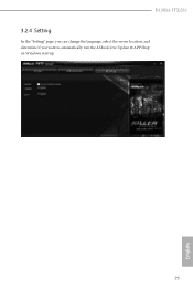
B150M-ITX/D3 3.2.4 Setting In the "Setting" page, you can change the language, select the server location, and determine if you want to automatically run the ASRock Live Update & APP Shop on Windows startup. 29 English
B150M-ITX/D3 3.2.4 Setting In the "Setting" page, you can change the language, select the server location, and determine if you want to automatically run the ASRock Live Update & APP Shop on Windows startup. 29 English
User Manual
Page 36
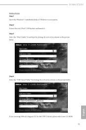
If you are using ASRock's Support CD for the USB 3.0 driver, please select your system. Step 4 Select the "USB Driver Folder" by clicking the red circle as shown as the picture below . Step 3 Select the "Win7 Folder" from Step1 by clicking the red circle as shown as the picture below . B150M-ITX/D3 Instructions Step 1 Insert the Windows® 7 installation disk or USB drive to your CD-ROM. 31 English Step 2 Extract the tool (Win7 USB Patcher) and launch it.
If you are using ASRock's Support CD for the USB 3.0 driver, please select your system. Step 4 Select the "USB Driver Folder" by clicking the red circle as shown as the picture below . Step 3 Select the "Win7 Folder" from Step1 by clicking the red circle as shown as the picture below . B150M-ITX/D3 Instructions Step 1 Insert the Windows® 7 installation disk or USB drive to your CD-ROM. 31 English Step 2 Extract the tool (Win7 USB Patcher) and launch it.
User Manual
Page 38
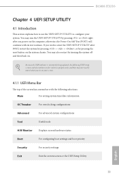
... or the UEFI Setup Utility English 33 You may also restart by turning the system of the screen has a menu bar with its test routines. B150M-ITX/D3 Chapter 4 UEFI SETUP UTILITY 4.1 Introduction his section explains how to use the UEFI SETUP UTILITY to enter the UEFI SETUP UTILITY ater POST, restart the...
... or the UEFI Setup Utility English 33 You may also restart by turning the system of the screen has a menu bar with its test routines. B150M-ITX/D3 Chapter 4 UEFI SETUP UTILITY 4.1 Introduction his section explains how to use the UEFI SETUP UTILITY to enter the UEFI SETUP UTILITY ater POST, restart the...

User Manual
Page 40
B150M-ITX/D3 4.2 Main Screen When you enter the UEFI SETUP UTILITY, the Main screen will appear and display the system overview. Favorite Display your collection of BIOS items. Press F5 to add/remove your favorite items. 35 English
B150M-ITX/D3 4.2 Main Screen When you enter the UEFI SETUP UTILITY, the Main screen will appear and display the system overview. Favorite Display your collection of BIOS items. Press F5 to add/remove your favorite items. 35 English
User Manual
Page 42
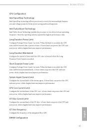
... exceeded, the CPU ratio will be lowered immediately. DRAM Coniguration 37 English System Agent Current Limit Conigure the current limit of the integrated Slice GPU. B150M-ITX/D3 CPU Coniguration Intel SpeedStep Technology Intel SpeedStep technology allows processors to run above its base operating frequency when the operating system requests the highest performance...
... exceeded, the CPU ratio will be lowered immediately. DRAM Coniguration 37 English System Agent Current Limit Conigure the current limit of the integrated Slice GPU. B150M-ITX/D3 CPU Coniguration Intel SpeedStep Technology Intel SpeedStep technology allows processors to run above its base operating frequency when the operating system requests the highest performance...

User Manual
Page 44
... of clocks that must elapse ater the completion of a valid write operation, before an active bank can be precharged. Read to the same internal bank. B150M-ITX/D3 Write Recovery Time (tWR) he amount of delay that are allowed the same rank. Write to Read Delay (tWTR_L) he number of clocks between the...
... of clocks that must elapse ater the completion of a valid write operation, before an active bank can be precharged. Read to the same internal bank. B150M-ITX/D3 Write Recovery Time (tWR) he amount of delay that are allowed the same rank. Write to Read Delay (tWTR_L) he number of clocks between the...