RAID Installation Guide
Page 2
Guide to create RAID on this motherboard for internal storage devices. This section will guide you how to SATA Hard Disks Installation 1.1 Serial ATA (SATA) Hard Disks Installation This motherboard adopts nVidia nForce3 chipset that supports Serial ATA (SATA) hard disks with RAID functions, including RAID 0, RAID 1, and JBOD. 1. For SATA installation guide, please refer to Serial ATA (SATA) Hard Disks Installation of "U ser Manual " in the support CD. You may install SATA hard disks on SATA ports. 2
Guide to create RAID on this motherboard for internal storage devices. This section will guide you how to SATA Hard Disks Installation 1.1 Serial ATA (SATA) Hard Disks Installation This motherboard adopts nVidia nForce3 chipset that supports Serial ATA (SATA) hard disks with RAID functions, including RAID 0, RAID 1, and JBOD. 1. For SATA installation guide, please refer to Serial ATA (SATA) Hard Disks Installation of "U ser Manual " in the support CD. You may install SATA hard disks on SATA ports. 2
RAID Installation Guide
Page 4
... two independent Serial ATA (SATA) channels. This section will cause data damage or data loss. 4 For optimal performance, please install identical drives of RAID This motherboard adopts nVidia nForce3 chipset that optimizes two identical hard disk drives to RAID Configurations 2.1 Introduction of the same model and capacity when creating a RAID set...
... two independent Serial ATA (SATA) channels. This section will cause data damage or data loss. 4 For optimal performance, please install identical drives of RAID This motherboard adopts nVidia nForce3 chipset that optimizes two identical hard disk drives to RAID Configurations 2.1 Introduction of the same model and capacity when creating a RAID set...
User Manual
Page 3
... 36 3.4 Hardware Health Event Monitoring Screen 36 3.5 Boot Screen 37 3.5.1 Boot Settings Configuration 37 3.6 Security Screen 38 3.7 Exit Screen 39 3 Introduction 5 1.1 Package Contents 5 1.2 Specifications 6 1.3 Motherboard Layout 9 1.4 ASRock 8CH I/O 10 2 . Installation 11 Pre-installation Precautions 11 2.1 CPU Installation 12 2.2 Installation of CPU Fan and Heatsink 12 2.3 Installation of Memory Modules (DIMM 13 2.4 Expansion...
... 36 3.4 Hardware Health Event Monitoring Screen 36 3.5 Boot Screen 37 3.5.1 Boot Settings Configuration 37 3.6 Security Screen 38 3.7 Exit Screen 39 3 Introduction 5 1.1 Package Contents 5 1.2 Specifications 6 1.3 Motherboard Layout 9 1.4 ASRock 8CH I/O 10 2 . Installation 11 Pre-installation Precautions 11 2.1 CPU Installation 12 2.2 Installation of CPU Fan and Heatsink 12 2.3 Installation of Memory Modules (DIMM 13 2.4 Expansion...

User Manual
Page 5
...subject to the hardware installation. ASRock website http://www.asrock.com 1.1 Package Contents 1 x ASRock 939NF4G-SATA2 Motherboard (Micro ATX Form Factor: 9.6-in x 8.8-in, 24.4 cm x 22.4 cm) 1 x ASRock 939NF4G-SATA2 Quick Installation Guide 1 x ASRock 939NF4G-SATA2 Support CD 1 x Ultra ... 1 x Serial ATA (SATA) HDD Power Cable (Optional) 1 x ASRock 8CH I/O Shield 1 x COM Port Bracket 5 Introduction Thank you for purchasing ASRock 939NF4G-SATA2 motherboard, a reliable motherboard produced under ASRock's consistently stringent quality control. Chapter 3 and 4 contain the configuration guide ...
...subject to the hardware installation. ASRock website http://www.asrock.com 1.1 Package Contents 1 x ASRock 939NF4G-SATA2 Motherboard (Micro ATX Form Factor: 9.6-in x 8.8-in, 24.4 cm x 22.4 cm) 1 x ASRock 939NF4G-SATA2 Quick Installation Guide 1 x ASRock 939NF4G-SATA2 Support CD 1 x Ultra ... 1 x Serial ATA (SATA) HDD Power Cable (Optional) 1 x ASRock 8CH I/O Shield 1 x COM Port Bracket 5 Introduction Thank you for purchasing ASRock 939NF4G-SATA2 motherboard, a reliable motherboard produced under ASRock's consistently stringent quality control. Chapter 3 and 4 contain the configuration guide ...
User Manual
Page 7
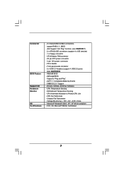
... BIOS Feature Support CD Hardware Monitor OS Certifications - 2 x Serial ATAII 3.0Gb/s connectors, support RAID 0, 1, JBOD (Not Support "Hot Plug" function) (see CAUTION 8) - 4Mb AMI BIOS - Motherboard Temperature Sensing -
... BIOS Feature Support CD Hardware Monitor OS Certifications - 2 x Serial ATAII 3.0Gb/s connectors, support RAID 0, 1, JBOD (Not Support "Hot Plug" function) (see CAUTION 8) - 4Mb AMI BIOS - Motherboard Temperature Sensing -
User Manual
Page 8
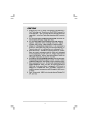
... 13 for proper installation. 4. You can support AMD's Cool 'n' QuietTM technology, please check AMD's website for details. 3. This motherboard supports Untied Overclocking Technology. Before you are allowed to downgrade the SATAII hard disk to SATA hard disk (from SATAII 3Gb/s down to...other than the recommended CPU bus frequencies may cause the instability of memory modules on page 23 for details. 2. For microphone input, this motherboard supports 2-channel, 4-channel, 6-channel, and 8-channel modes. Besides, you implement Dual Channel Memory Technology, make sure to enable AMD's...
... 13 for proper installation. 4. You can support AMD's Cool 'n' QuietTM technology, please check AMD's website for details. 3. This motherboard supports Untied Overclocking Technology. Before you are allowed to downgrade the SATAII hard disk to SATA hard disk (from SATAII 3Gb/s down to...other than the recommended CPU bus frequencies may cause the instability of memory modules on page 23 for details. 2. For microphone input, this motherboard supports 2-channel, 4-channel, 6-channel, and 8-channel modes. Besides, you implement Dual Channel Memory Technology, make sure to enable AMD's...

User Manual
Page 11
...components by the edges and do so may damage the motherboard. 11 When placing screws into it on the carpet or the like. Installation 939NF4G-SATA2 is detached from the wall socket before you install the motherboard, study the configuration of the following precautions before you ...install or remove any component, place it . Failure to the motherboard, peripherals, and/or components. 1. Also ...
...components by the edges and do so may damage the motherboard. 11 When placing screws into it on the carpet or the like. Installation 939NF4G-SATA2 is detached from the wall socket before you install the motherboard, study the configuration of the following precautions before you ...install or remove any component, place it . Failure to the motherboard, peripherals, and/or components. 1. Also ...

User Manual
Page 12
... necessary to install a larger heatsink and cooling fan to secure the CPU. The lever clicks on the socket while you install the CPU into this motherboard, it is in place. Then connect the CPU fan to improve heat dissipation. For proper installation, please kindly refer to indicate that the CPU corner...
... necessary to install a larger heatsink and cooling fan to secure the CPU. The lever clicks on the socket while you install the CPU into this motherboard, it is in place. Then connect the CPU fan to improve heat dissipation. For proper installation, please kindly refer to indicate that the CPU corner...

User Manual
Page 13
...other words, you always need to activate the Dual Channel Memory Technology . 13 2.3 Installation of the same color. Blue slots; Black slots; This motherboard also allows you want to install two memory modules, for example, installing a pair of memory modules in DDR1 and DDR3, it is unable to install... Populated Populated Populated Populated * For the configuration (3), please install identical DDR DIMMs in the slots of Memory Modules (DIMM) 939NF4G-SATA2 motherboard provides four 184-pin DDR (Double Data Rate) DIMM slots, and supports Dual Channel Memory Technology.
...other words, you always need to activate the Dual Channel Memory Technology . 13 2.3 Installation of the same color. Blue slots; Black slots; This motherboard also allows you want to install two memory modules, for example, installing a pair of memory modules in DDR1 and DDR3, it is unable to install... Populated Populated Populated Populated * For the configuration (3), please install identical DDR DIMMs in the slots of Memory Modules (DIMM) 939NF4G-SATA2 motherboard provides four 184-pin DDR (Double Data Rate) DIMM slots, and supports Dual Channel Memory Technology.

User Manual
Page 14
... a DIMM on the slot such that the notch on the DIMM matches the break on the slot. Step 3. Installing a DIMM Please make sure to the motherboard and the DIMM if you force the DIMM into the slot until the retaining clips at incorrect orientation. Unlock a DIMM slot by pressing the retaining...
... a DIMM on the slot such that the notch on the DIMM matches the break on the slot. Step 3. Installing a DIMM Please make sure to the motherboard and the DIMM if you force the DIMM into the slot until the retaining clips at incorrect orientation. Unlock a DIMM slot by pressing the retaining...

User Manual
Page 15
.... Step 3. Replace the system cover. 2.5 Easy Multi Monitor Feature This motherboard supports Multi Monitor upgrade. Step 5. Step 6. With the internal onboard VGA and the external add-on PCI Express VGA card, you intend to insert an ASRock MR card with x16 lane width graphics cards. PCIE2 (PCIE x 1 ... (PCIE x 16 slot) is used for the card before you can easily enjoy the benefits of "Share Memory" is completely seated on 939NF4G-SATA2 motherboard. Please note that have the 32-bit PCI interface. If you select should be less than the total capability of BIOS to adjust the...
.... Step 3. Replace the system cover. 2.5 Easy Multi Monitor Feature This motherboard supports Multi Monitor upgrade. Step 5. Step 6. With the internal onboard VGA and the external add-on PCI Express VGA card, you intend to insert an ASRock MR card with x16 lane width graphics cards. PCIE2 (PCIE x 1 ... (PCIE x 16 slot) is used for the card before you can easily enjoy the benefits of "Share Memory" is completely seated on 939NF4G-SATA2 motherboard. Please note that have the 32-bit PCI interface. If you select should be less than the total capability of BIOS to adjust the...

User Manual
Page 17
... to the primary IDE connector (IDE1, blue) and CD-ROM to the SATA / SATAII hard disk or the SATAII connector on this motherboard, please set the IDE device as "Master". 2.7 Onboard Headers and Connectors Onboard headers and connectors are NOT jumpers. Placing jumper caps over..., to optimize compatibility and performance, please connect your IDE device vendor for internal storage devices. Serial ATA (SATA) Data Cable Either end of the motherboard! • Floppy Connector (33-pin FLOPPY1) (see p.9, No. 12) SATAII_2 SATAII_1 These Serial ATA II (SATA II) connectors support SATA II...
... to the primary IDE connector (IDE1, blue) and CD-ROM to the SATA / SATAII hard disk or the SATAII connector on this motherboard, please set the IDE device as "Master". 2.7 Onboard Headers and Connectors Onboard headers and connectors are NOT jumpers. Placing jumper caps over..., to optimize compatibility and performance, please connect your IDE device vendor for internal storage devices. Serial ATA (SATA) Data Cable Either end of the motherboard! • Floppy Connector (33-pin FLOPPY1) (see p.9, No. 12) SATAII_2 SATAII_1 These Serial ATA II (SATA II) connectors support SATA II...

User Manual
Page 21
... the SATA power cable to install the SATA / SATAII hard disks. 2.9 Serial ATA (SATA) / Serial ATAII (SATAII) Hard Disks Installation This motherboard adopts nVidia nForce 410 MCP southbridge chipset that supports Serial ATA (SATA) / Serial ATAII (SATAII) hard disks and RAID functions. You may install ...SATA / SATAII hard disks on this motherboard for internal storage devices. This section will guide you to the SATA / SATAII hard disk. STEP 1: Install the SATA / SATAII hard disks into...
... the SATA power cable to install the SATA / SATAII hard disks. 2.9 Serial ATA (SATA) / Serial ATAII (SATAII) Hard Disks Installation This motherboard adopts nVidia nForce 410 MCP southbridge chipset that supports Serial ATA (SATA) / Serial ATAII (SATAII) hard disks and RAID functions. You may install ...SATA / SATAII hard disks on this motherboard for internal storage devices. This section will guide you to the SATA / SATAII hard disk. STEP 1: Install the SATA / SATAII hard disks into...
User Manual
Page 23
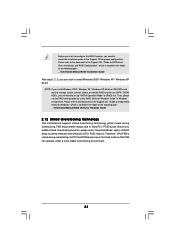
... 2000 / Windows XP / Windows XP 64-bit. Then, please set the RAID configuration by using "RAID Utility for Windows Guide 2.12 Untied Overclocking Technology This motherboard supports Untied Overclocing Technology, which means during overclocking, but PCI and PCIE buses are in the fixed mode so that FSB can start to configure...
... 2000 / Windows XP / Windows XP 64-bit. Then, please set the RAID configuration by using "RAID Utility for Windows Guide 2.12 Untied Overclocking Technology This motherboard supports Untied Overclocing Technology, which means during overclocking, but PCI and PCIE buses are in the fixed mode so that FSB can start to configure...

User Manual
Page 24
... after POST, restart the system by pressing + + , or by turning the system off and then back on the system chassis. If you see on the motherboard stores the BIOS SETUP UTILITY. Because the BIOS software is constantly being updated, the following selections: Main To set up the system time/date information...
... after POST, restart the system by pressing + + , or by turning the system off and then back on the system chassis. If you see on the motherboard stores the BIOS SETUP UTILITY. Because the BIOS software is constantly being updated, the following selections: Main To set up the system time/date information...

User Manual
Page 36
... Exit Exit v02.54 (C) Copyright 1985-2003, American Megatrends, Inc. USB 2.0 Support Use this item to enable or disable the use of the CPU temperature, motherboard temperature, CPU fan speed, chassis fan speed, and the critical voltage. etc. USB Controller Use this item to emulate the I/O devices of legacy OS (DOS...
... Exit Exit v02.54 (C) Copyright 1985-2003, American Megatrends, Inc. USB 2.0 Support Use this item to enable or disable the use of the CPU temperature, motherboard temperature, CPU fan speed, chassis fan speed, and the critical voltage. etc. USB Controller Use this item to emulate the I/O devices of legacy OS (DOS...

User Manual
Page 40
...2000 / XP / XP 64-bit. Refer to activate the devices. 4.2.3 Utilities Menu The Utilities Menu shows the applications software that enhance the motherboard features. 4.2.1 Running The Support CD To begin using the support CD, insert the CD into your OS documentation for general reference only. Please ...the file "ASSETUP.EXE" from the BIN folder in this chapter for more about ASRock, welcome to display the menus. 4.2.2 Drivers Menu The Drivers Menu shows the available devices drivers including ASRock Express GbL PCI Express LAN card driver if the system detects the installed devices. or...
...2000 / XP / XP 64-bit. Refer to activate the devices. 4.2.3 Utilities Menu The Utilities Menu shows the applications software that enhance the motherboard features. 4.2.1 Running The Support CD To begin using the support CD, insert the CD into your OS documentation for general reference only. Please ...the file "ASSETUP.EXE" from the BIN folder in this chapter for more about ASRock, welcome to display the menus. 4.2.2 Drivers Menu The Drivers Menu shows the available devices drivers including ASRock Express GbL PCI Express LAN card driver if the system detects the installed devices. or...

Quick Installation Guide
Page 1
...respective companies, and are furnished for informational use only and subject to the owners' benefit, without written consent of ASRock Inc. Disclaimer: Specifications and information contained in this guide are used only for any errors or omissions that may not...change without notice, and should not be constructed as a commitment by ASRock. This device complies with Part 15 of the FCC Rules. All rights reserved. 1 ASRock 939NF4G-SATA2 Motherboard English ASRock assumes no event shall ASRock, its directors, officers, employees, or agents be reproduced, transcribed, ...
...respective companies, and are furnished for informational use only and subject to the owners' benefit, without written consent of ASRock Inc. Disclaimer: Specifications and information contained in this guide are used only for any errors or omissions that may not...change without notice, and should not be constructed as a commitment by ASRock. This device complies with Part 15 of the FCC Rules. All rights reserved. 1 ASRock 939NF4G-SATA2 Motherboard English ASRock assumes no event shall ASRock, its directors, officers, employees, or agents be reproduced, transcribed, ...

Quick Installation Guide
Page 2
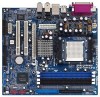
... (SPEAKER 1) 31 ATX Power Connector (ATXPWR1) 15 Chassis Fan Connector (CHA_FAN1) 32 Serial Port Connector (COM1) 2 ASRock 939NF4G-SATA2 Motherboard Blue) 22 Flash Memory 7 2 x 184-pin DDR DIMM Slots 23 Game Port Header (GAME1) (Dual Channel B: DDR3, DDR4; Motherboard Layout English 1 PS2_USB_PW1 Jumper 16 System Panel Header (PANEL1) 2 ATX 12V Power Connector (ATX12V1) 17 USB...
... (SPEAKER 1) 31 ATX Power Connector (ATXPWR1) 15 Chassis Fan Connector (CHA_FAN1) 32 Serial Port Connector (COM1) 2 ASRock 939NF4G-SATA2 Motherboard Blue) 22 Flash Memory 7 2 x 184-pin DDR DIMM Slots 23 Game Port Header (GAME1) (Dual Channel B: DDR3, DDR4; Motherboard Layout English 1 PS2_USB_PW1 Jumper 16 System Panel Header (PANEL1) 2 ATX 12V Power Connector (ATX12V1) 17 USB...

Quick Installation Guide
Page 3
See the table below for Audio Output Connection Audio Output Channels Front Speaker Rear Speaker Central / Bass (No. 7) (No. 4) (No. 5) 2 V -- -- 4 V V -- 6 V V V 8 V V V Side Speaker (No. 3) ---V 3 ASRock 939NF4G-SATA2 Motherboard English ASRock 8CH I/O 1 Parallel Port 2 RJ-45 Port 3 Side Speaker (Gray) 4 Rear Speaker (Black) 5 Central / Bass (Orange) 6 Line In (Light Blue) *7 Front Speaker (Lime) 8 Microphone (Pink) 9 USB 2.0 ...
See the table below for Audio Output Connection Audio Output Channels Front Speaker Rear Speaker Central / Bass (No. 7) (No. 4) (No. 5) 2 V -- -- 4 V V -- 6 V V V 8 V V V Side Speaker (No. 3) ---V 3 ASRock 939NF4G-SATA2 Motherboard English ASRock 8CH I/O 1 Parallel Port 2 RJ-45 Port 3 Side Speaker (Gray) 4 Rear Speaker (Black) 5 Central / Bass (Orange) 6 Line In (Light Blue) *7 Front Speaker (Lime) 8 Microphone (Pink) 9 USB 2.0 ...

