RAID Installation Guide
Page 1
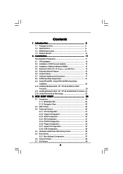
Guide to SATA Hard Disks Installation 2 1.1 Serial ATA (SATA) Hard Disks Installation 2 1.2 Making a SATA Driver Diskette 3 2. Guide to RAID Configurations 4 2.1 Introduction of RAID 4 2.2 RAID Configuration Precautions 6 2.3 BIOS Configuration Utility 7 2.3.1 Enter BIOS Configuration Utility 7 2.3.2 Create Disk Array 8 1 Guide to SATA Hard Disks Installation and RAID Configuration 1.
Guide to SATA Hard Disks Installation 2 1.1 Serial ATA (SATA) Hard Disks Installation 2 1.2 Making a SATA Driver Diskette 3 2. Guide to RAID Configurations 4 2.1 Introduction of RAID 4 2.2 RAID Configuration Precautions 6 2.3 BIOS Configuration Utility 7 2.3.1 Enter BIOS Configuration Utility 7 2.3.2 Create Disk Array 8 1 Guide to SATA Hard Disks Installation and RAID Configuration 1.
RAID Installation Guide
Page 3
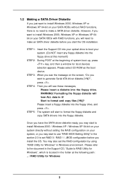
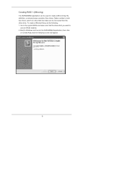
STEP 5: The system will start to use "RAID BIOS Setting Utility" in the section 2.3 to set the RAID configuration by using "RAID Utility for Windows" in the Support CD, "Guide to format the floppy ...
STEP 5: The system will start to use "RAID BIOS Setting Utility" in the section 2.3 to set the RAID configuration by using "RAID Utility for Windows" in the Support CD, "Guide to format the floppy ...
RAID Installation Guide
Page 7
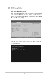
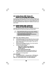
...]. Press F10 to enter the NVIDIA RAID Utility. American Megatrends, Inc. Advanced BIOS SETUP UTILITY IDE Configuration OnBoard IDE Controller OnBoard SATA Controller SATA Operation Mode Primary IDE Master Primary IDE Slave Secondary IDE Master Secondary IDE Slave SATA1 SATA2 [Both] [Enabled] [RAID] [Hard Disk] [Not Detected] [ATAPI CDROM] [Not Detected] [Not...
...]. Press F10 to enter the NVIDIA RAID Utility. American Megatrends, Inc. Advanced BIOS SETUP UTILITY IDE Configuration OnBoard IDE Controller OnBoard SATA Controller SATA Operation Mode Primary IDE Master Primary IDE Slave Secondary IDE Master Secondary IDE Slave SATA1 SATA2 [Both] [Enabled] [RAID] [Hard Disk] [Not Detected] [ATAPI CDROM] [Not Detected] [Not...
RAID Installation Guide
Page 8
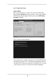
...RAID setup utility . . . You have a few seconds to [RAID]. NVIDIA RAID IDE ROM BIOS 4.81 Copyright (C) 2004 NVIDIA Corp. The RAID prompt appears as a part of BIOS setup utility will appear. Please set the option SATA Opera tion Mode to press before the window ...disappears. 8 Advanced BIOS SETUP UTILITY IDE Configuration OnBoard IDE Controller OnBoard SATA Controller SATA Operation Mode Primary IDE Master Primary IDE Slave Secondary IDE Master Secondary IDE Slave SATA1 SATA2 [Both] [Enabled] [RAID] [Hard Disk] [Not Detected]...
...RAID setup utility . . . You have a few seconds to [RAID]. NVIDIA RAID IDE ROM BIOS 4.81 Copyright (C) 2004 NVIDIA Corp. The RAID prompt appears as a part of BIOS setup utility will appear. Please set the option SATA Opera tion Mode to press before the window ...disappears. 8 Advanced BIOS SETUP UTILITY IDE Configuration OnBoard IDE Controller OnBoard SATA Controller SATA Operation Mode Primary IDE Master Primary IDE Slave Secondary IDE Master Secondary IDE Slave SATA1 SATA2 [Both] [Enabled] [RAID] [Hard Disk] [Not Detected]...

RAID Installation Guide
Page 10
... 8KB and 128KB (8, 16, 32, 64, and 128KB). The first disk in the list is arranged on the disk. Move it from the RAID Config BIOS setup page appear in the Array Disks block. RAID Mode : Striping Free Disks Loc Disk Model Name Stripimg Block : Optimal Array Disks Loc Disk Model...
... 8KB and 128KB (8, 16, 32, 64, and 128KB). The first disk in the list is arranged on the disk. Move it from the RAID Config BIOS setup page appear in the Array Disks block. RAID Mode : Striping Free Disks Loc Disk Model Name Stripimg Block : Optimal Array Disks Loc Disk Model...
RAID Installation Guide
Page 12
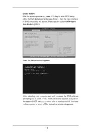
...You have a few seconds to press . Please set the option SATA Opera tion Mode to enter RAID setup utility . . . NVIDIA RAID IDE ROM BIOS 4.81 Copyright (C) 2004 NVIDIA Corp. Detecting array . . . 0 Healthy NVIDIA RAID 1 74.54G Press F10 to [RAID]. Highlight Advanced and press ...After the system powers on, press key to loading the OS. Advanced BIOS SETUP UTILITY IDE Configuration OnBoard IDE Controller OnBoard SATA Controller SATA Operation Mode Primary IDE Master Primary IDE Slave Secondary IDE Master Secondary IDE Slave SATA1 SATA2 [Both] [Enabled] [RAID] [Hard Disk] [Not Detected] ...
...You have a few seconds to press . Please set the option SATA Opera tion Mode to enter RAID setup utility . . . NVIDIA RAID IDE ROM BIOS 4.81 Copyright (C) 2004 NVIDIA Corp. Detecting array . . . 0 Healthy NVIDIA RAID 1 74.54G Press F10 to [RAID]. Highlight Advanced and press ...After the system powers on, press key to loading the OS. Advanced BIOS SETUP UTILITY IDE Configuration OnBoard IDE Controller OnBoard SATA Controller SATA Operation Mode Primary IDE Master Primary IDE Slave Secondary IDE Master Secondary IDE Slave SATA1 SATA2 [Both] [Enabled] [RAID] [Hard Disk] [Not Detected] ...
RAID Installation Guide
Page 15
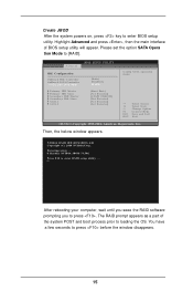
... utility. Advanced BIOS SETUP UTILITY IDE Configuration OnBoard IDE Controller OnBoard SATA Controller SATA Operation Mode Primary IDE Master Primary IDE Slave Secondary IDE Master Secondary IDE Slave SATA1 SATA2 [Both] [Enabled] [RAID] [Hard Disk] [Not Detected] [ATAPI CDROM] [Not Detected] [Not Detected] [Not Detected] Config SATA operation mode. +F1 F10 ESC...
... utility. Advanced BIOS SETUP UTILITY IDE Configuration OnBoard IDE Controller OnBoard SATA Controller SATA Operation Mode Primary IDE Master Primary IDE Slave Secondary IDE Master Secondary IDE Slave SATA1 SATA2 [Both] [Enabled] [RAID] [Hard Disk] [Not Detected] [ATAPI CDROM] [Not Detected] [Not Detected] [Not Detected] Config SATA operation mode. +F1 F10 ESC...
RAID Utility for Windows Guide
Page 2
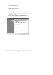
Boot to the maximum supported number of disks in the system. Creating RAID Arrays Creating RAID 0 (Striping) NVRAIDMAN can be used to create a striped array from one disk up to Windows and launch the NVRAIDMAN application. 3. Create Array and the following . 1. Go to the system BIOS and make sure that the drives that you want to use are RAID enabled. 2. 2. To create a twodisk Striped Array do the following screen will appear. 2
Boot to the maximum supported number of disks in the system. Creating RAID Arrays Creating RAID 0 (Striping) NVRAIDMAN can be used to create a striped array from one disk up to Windows and launch the NVRAIDMAN application. 3. Create Array and the following . 1. Go to the system BIOS and make sure that the drives that you want to use are RAID enabled. 2. 2. To create a twodisk Striped Array do the following screen will appear. 2
RAID Utility for Windows Guide
Page 6
Data is written to both two drives, and if one drive fails then data can be recovered from the other drive. Go to the system BIOS and make sure that the drives that you want to Windows and launch the NVRAIDMAN application, then click on Create Array and the following . 1. By definition, a mirrored array consists of two drives. To create a Mirrored Array, do the following screen will appear. 6 Creating RAID 1 (Mirroring) The NVRAIDMAN application can be used to create a Mirror Array. Boot to use are RAID enabled. 2.
Data is written to both two drives, and if one drive fails then data can be recovered from the other drive. Go to the system BIOS and make sure that the drives that you want to Windows and launch the NVRAIDMAN application, then click on Create Array and the following . 1. By definition, a mirrored array consists of two drives. To create a Mirrored Array, do the following screen will appear. 6 Creating RAID 1 (Mirroring) The NVRAIDMAN application can be used to create a Mirror Array. Boot to use are RAID enabled. 2.

RAID Utility for Windows Guide
Page 10
Boot to Windows and launch the NVRAIDMAN application, then click on Create Array and the following screen will appear. 3. Click Next and the following screen will appear. 10 Creating JBOD (Spanning) NVRAIDMAN can be used to create a Spanning Array which requires at least one disk to use are RAID enabled. 2. Go to the system BIOS and make sure that the drives that you want to start such an array. To create a Spanning Array do the following: 1.
Boot to Windows and launch the NVRAIDMAN application, then click on Create Array and the following screen will appear. 3. Click Next and the following screen will appear. 10 Creating JBOD (Spanning) NVRAIDMAN can be used to create a Spanning Array which requires at least one disk to use are RAID enabled. 2. Go to the system BIOS and make sure that the drives that you want to start such an array. To create a Spanning Array do the following: 1.
User Manual
Page 3
... 24 3.1 Introduction 24 3.1.1 BIOS Menu Bar 24 3.1.2 Navigation Keys 25 3.2 Main Screen 25 3.3 Advanced Screen 26 3.3.1 CPU Configuration 27 3.3.2 Chipset Configuration 29 3.3.3 ACPI ...3.5 Boot Screen 37 3.5.1 Boot Settings Configuration 37 3.6 Security Screen 38 3.7 Exit Screen 39 3 Introduction 5 1.1 Package Contents 5 1.2 Specifications 6 1.3 Motherboard Layout 9 1.4 ASRock 8CH I/O 10 2 . Installation 11 Pre-installation Precautions 11 2.1 CPU Installation 12 2.2 Installation of CPU Fan and Heatsink 12 2.3 Installation of Memory Modules (DIMM 13 2.4 Expansion...
... 24 3.1 Introduction 24 3.1.1 BIOS Menu Bar 24 3.1.2 Navigation Keys 25 3.2 Main Screen 25 3.3 Advanced Screen 26 3.3.1 CPU Configuration 27 3.3.2 Chipset Configuration 29 3.3.3 ACPI ...3.5 Boot Screen 37 3.5.1 Boot Settings Configuration 37 3.6 Security Screen 38 3.7 Exit Screen 39 3 Introduction 5 1.1 Package Contents 5 1.2 Specifications 6 1.3 Motherboard Layout 9 1.4 ASRock 8CH I/O 10 2 . Installation 11 Pre-installation Precautions 11 2.1 CPU Installation 12 2.2 Installation of CPU Fan and Heatsink 12 2.3 Installation of Memory Modules (DIMM 13 2.4 Expansion...

User Manual
Page 5
... without further notice. You may find the latest memory and CPU support lists on ASRock website without notice. Introduction Thank you for purchasing ASRock 939NF4G-SATA2 motherboard, a reliable motherboard produced under ASRock's consistently stringent quality control. Because the motherboard specifications and the BIOS software might be updated, the content of this manual will be subject to...
... without further notice. You may find the latest memory and CPU support lists on ASRock website without notice. Introduction Thank you for purchasing ASRock 939NF4G-SATA2 motherboard, a reliable motherboard produced under ASRock's consistently stringent quality control. Because the motherboard specifications and the BIOS software might be updated, the content of this manual will be subject to...
User Manual
Page 7
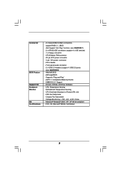
... - CPU Temperature Sensing - CPU Fan Tachometer - FCC, CE, Microsoft® WHQL Certificated 7 CPU Overheat Shutdown to Protect CPU Life - AMI Legal BIOS - Drivers, Utilities, AntiVirus Software - Voltage Monitoring: +12V, +5V, +3.3V, Vcore - CD in header - Motherboard Temperature Sensing - Front panel... Wake Up Events - Chassis Fan Tachometer - Microsoft® Windows® 2000 / XP / XP 64-bit compliant - Connector BIOS Feature Support CD Hardware Monitor OS Certifications - 2 x Serial ATAII 3.0Gb/s connectors, support RAID 0, 1, JBOD (Not Support "Hot Plug" function) (see ...
... - CPU Temperature Sensing - CPU Fan Tachometer - FCC, CE, Microsoft® WHQL Certificated 7 CPU Overheat Shutdown to Protect CPU Life - AMI Legal BIOS - Drivers, Utilities, AntiVirus Software - Voltage Monitoring: +12V, +5V, +3.3V, Vcore - CD in header - Motherboard Temperature Sensing - Front panel... Wake Up Events - Chassis Fan Tachometer - Microsoft® Windows® 2000 / XP / XP 64-bit compliant - Connector BIOS Feature Support CD Hardware Monitor OS Certifications - 2 x Serial ATAII 3.0Gb/s connectors, support RAID 0, 1, JBOD (Not Support "Hot Plug" function) (see ...

User Manual
Page 15
AMR slot: The AMR slot is used to insert an ASRock MR card with the slot and press firmly until the card is...15 Step 5. With the internal onboard VGA and the external add-on 939NF4G-SATA2 motherboard. PCIE2 (PCIE x 1 slot) is used for PCI Express cards, such as Gigabit LAN card, SATA2 card, etc. Step 4. Please note that the value you intend to ...is already installed in a chassis). Fasten the card to the chassis with x16 lane width graphics cards. After setting up BIOS, you plan to enable the function of onboard VGA, please enter the option "Share Memory" of Multi Monitor feature. ...
AMR slot: The AMR slot is used to insert an ASRock MR card with the slot and press firmly until the card is...15 Step 5. With the internal onboard VGA and the external add-on 939NF4G-SATA2 motherboard. PCIE2 (PCIE x 1 slot) is used for PCI Express cards, such as Gigabit LAN card, SATA2 card, etc. Step 4. Please note that the value you intend to ...is already installed in a chassis). Fasten the card to the chassis with x16 lane width graphics cards. After setting up BIOS, you plan to enable the function of onboard VGA, please enter the option "Share Memory" of Multi Monitor feature. ...

User Manual
Page 16
..., both the front panel and the rear panel audio connectors can work. If you need to clear the CMOS when you just finish updating the BIOS, you to short pin2 and pin3 on these 2 pins. Clear CMOS Jumper (CLRCMOS1) (see p.9, No. 1) +5V +5VSB +5VSB (standby) for 5 seconds. The data in CMOS... boot up events. When the jumper cap is placed on pins, the jumper is "Short". Note: To select +5VSB, it down before you update the BIOS. If no jumper cap is placed on pins, the jumper is "Open".
..., both the front panel and the rear panel audio connectors can work. If you need to clear the CMOS when you just finish updating the BIOS, you to short pin2 and pin3 on these 2 pins. Clear CMOS Jumper (CLRCMOS1) (see p.9, No. 1) +5V +5VSB +5VSB (standby) for 5 seconds. The data in CMOS... boot up events. When the jumper cap is placed on pins, the jumper is "Short". Note: To select +5VSB, it down before you update the BIOS. If no jumper cap is placed on pins, the jumper is "Open".
User Manual
Page 22
... XP 64-bit on your SATA / SATAII HDDs with RAID functions, please follow the below website for boot devices selection appears. A. Enter BIOS SETUP UTILITY Advanced screen IDE Configuration. C. Start to [RAID]. STEP 3: Use "RAID Installation Guide" to boot your system. Besides, there... supposed to make a SATA / SATAII driver diskette. You can start to generate Serial ATA driver diskette [YN]?", press . Insert the ASRock Support CD into the floppy drive. When you see these messages, Please insert a diskette into your optical drive to set RAID configuration....
... XP 64-bit on your SATA / SATAII HDDs with RAID functions, please follow the below website for boot devices selection appears. A. Enter BIOS SETUP UTILITY Advanced screen IDE Configuration. C. Start to [RAID]. STEP 3: Use "RAID Installation Guide" to boot your system. Besides, there... supposed to make a SATA / SATAII driver diskette. You can start to generate Serial ATA driver diskette [YN]?", press . Insert the ASRock Support CD into the floppy drive. When you see these messages, Please insert a diskette into your optical drive to set RAID configuration....
User Manual
Page 23
NOTE. Before you enable Untied Overclocking function, please enter "Overclock Mode" option of BIOS setup to set the selection from [Auto] to fixed PCI / PCIE buses. Then, please set up "SATAII Operation Mode" to check the installation guide in ...
NOTE. Before you enable Untied Overclocking function, please enter "Overclock Mode" option of BIOS setup to set the selection from [Auto] to fixed PCI / PCIE buses. Then, please set up "SATAII Operation Mode" to check the installation guide in ...

User Manual
Page 24
...selections: Main To set up the system time/date information Advanced To set up the advanced BIOS features H/W Monitor To display current hardware status Boot To set up the default system device...Please press during the Power-On-Self-Test (POST) to enter the BIOS SETUP UTILITY, otherwise, POST will continue with the following BIOS setup screens and descriptions are for reference purpose only, and they may...into the sub screen. 24 If you see on the menu bar, and then press to enter the BIOS SETUP UTILITY after POST, restart the system by pressing + + , or by turning the system off ...
...selections: Main To set up the system time/date information Advanced To set up the advanced BIOS features H/W Monitor To display current hardware status Boot To set up the default system device...Please press during the Power-On-Self-Test (POST) to enter the BIOS SETUP UTILITY, otherwise, POST will continue with the following BIOS setup screens and descriptions are for reference purpose only, and they may...into the sub screen. 24 If you see on the menu bar, and then press to enter the BIOS SETUP UTILITY after POST, restart the system by pressing + + , or by turning the system off ...

User Manual
Page 25
... UTILITY Main Advanced H/W Monitor Boot Security Exit System Overview System Time [17:00:09] System Date [Tue 08/09/2005] BIOS Version : 939NF4G-SATA2 BIOS P1.0 Processor Type : AMD Athlon(tm) 64 Processor 3400+ (64bit supported) Processor Speed : 2200 MHz Microcode Update : F7A/3A L1 ... None : None Use [Enter], [TAB] or [SHIFT-TAB] to the Exit Screen or exit the current screen 3.2 Main Screen When you enter the BIOS SETUP UTILITY, the Main screen will appear and display the system overview. Navigation Key(s) / / + / Function Description Moves cursor left or right to select...
... UTILITY Main Advanced H/W Monitor Boot Security Exit System Overview System Time [17:00:09] System Date [Tue 08/09/2005] BIOS Version : 939NF4G-SATA2 BIOS P1.0 Processor Type : AMD Athlon(tm) 64 Processor 3400+ (64bit supported) Processor Speed : 2200 MHz Microcode Update : F7A/3A L1 ... None : None Use [Enter], [TAB] or [SHIFT-TAB] to the Exit Screen or exit the current screen 3.2 Main Screen When you enter the BIOS SETUP UTILITY, the Main screen will appear and display the system overview. Navigation Key(s) / / + / Function Description Moves cursor left or right to select...

User Manual
Page 26
Overclock Mode Use this option to malfunction. 3.3.1 CPU Configuration BIOS SETUP UTILITY Advanced CPU Configuration Overclock Mode CPU Frequency (MHz) PCIE Frequency (MHz) Boot Failure Guard CPU Spread Spectrum PCIE Spread Spectrum SATA Spread ...F10 ESC Select Screen Select Item Change Option General Help Load Defaults Save and Exit Exit v02.54 (C) Copyright 1985-2003, American Megatrends, Inc. Main BIOS SETUP UTILITY Advanced H/W Monitor Boot Security Exit Advanced Settings WARNING : Setting wrong values in this section may cause system to 300MHz. If Manual, multiplier and...
Overclock Mode Use this option to malfunction. 3.3.1 CPU Configuration BIOS SETUP UTILITY Advanced CPU Configuration Overclock Mode CPU Frequency (MHz) PCIE Frequency (MHz) Boot Failure Guard CPU Spread Spectrum PCIE Spread Spectrum SATA Spread ...F10 ESC Select Screen Select Item Change Option General Help Load Defaults Save and Exit Exit v02.54 (C) Copyright 1985-2003, American Megatrends, Inc. Main BIOS SETUP UTILITY Advanced H/W Monitor Boot Security Exit Advanced Settings WARNING : Setting wrong values in this section may cause system to 300MHz. If Manual, multiplier and...


