
User Manual
Page 2
...Management Practices (BMP) regulations passed by ASRock. CALIFORNIA, USA ONLY The Lithium battery adopted on this manual, ASRock does not provide warranty of any kind, either expressed or implied, including but not limited to the contents of this motherboard contains Perchlorate, a toxic substance controlled ... of such damages arising from any errors or omissions that may apply, see www.dtsc.ca.gov/hazardouswaste/perchlorate" ASRock Website: http://www.asrock.com 2 When you discard the Lithium battery in California, USA, please follow the related regulations in this device must...
...Management Practices (BMP) regulations passed by ASRock. CALIFORNIA, USA ONLY The Lithium battery adopted on this manual, ASRock does not provide warranty of any kind, either expressed or implied, including but not limited to the contents of this motherboard contains Perchlorate, a toxic substance controlled ... of such damages arising from any errors or omissions that may apply, see www.dtsc.ca.gov/hazardouswaste/perchlorate" ASRock Website: http://www.asrock.com 2 When you discard the Lithium battery in California, USA, please follow the related regulations in this device must...
User Manual
Page 3
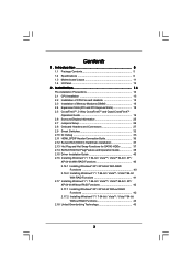
... 42 2.17.2 Installing Windows® 7 / 7 64-bit / VistaTM / VistaTM 64-bit Without RAID Functions 43 2.18 Untied Overclocking Technology 43 3 Contents 1 . Introduction 5 1.1 Package Contents 5 1.2 Specifications 6 1.3 Motherboard Layout 11 1.4 I/O Panel 12 2 .
... 42 2.17.2 Installing Windows® 7 / 7 64-bit / VistaTM / VistaTM 64-bit Without RAID Functions 43 2.18 Untied Overclocking Technology 43 3 Contents 1 . Introduction 5 1.1 Package Contents 5 1.2 Specifications 6 1.3 Motherboard Layout 11 1.4 I/O Panel 12 2 .

User Manual
Page 5
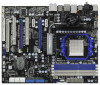
.../support/index.asp 1.1 Package Contents ASRock 890FX Deluxe3 Motherboard (ATX Form Factor: 12.0-in x 9.6-in, 30.5 cm x 24.4 cm) ASRock 890FX Deluxe3 Quick Installation Guide ASRock 890FX Deluxe3 Support CD 1 x Ultra ATA 66/100/133 IDE Ribbon Cable (80-conductor) 1 x Ribbon Cable for purchasing ASRock 890FX Deluxe3 motherboard, a reliable motherboard produced under ASRock's consistently stringent quality control. ASRock website http://www.asrock.com If you for a 3.5-in Floppy...
.../support/index.asp 1.1 Package Contents ASRock 890FX Deluxe3 Motherboard (ATX Form Factor: 12.0-in x 9.6-in, 30.5 cm x 24.4 cm) ASRock 890FX Deluxe3 Quick Installation Guide ASRock 890FX Deluxe3 Support CD 1 x Ultra ATA 66/100/133 IDE Ribbon Cable (80-conductor) 1 x Ribbon Cable for purchasing ASRock 890FX Deluxe3 motherboard, a reliable motherboard produced under ASRock's consistently stringent quality control. ASRock website http://www.asrock.com If you for a 3.5-in Floppy...
User Manual
Page 9
.... Due to enjoy an instant performance boost. Please visit our website for system usage under Windows® environment. This motherboard supports Untied Overclocking Technology. ASRock website http://www.asrock.com 5. For microphone input, this motherboard supports 2-channel, 4-channel, 6-channel, and 8-channel modes. Please check the table on page 16 for details. 3. To use Intelligent...
.... Due to enjoy an instant performance boost. Please visit our website for system usage under Windows® environment. This motherboard supports Untied Overclocking Technology. ASRock website http://www.asrock.com 5. For microphone input, this motherboard supports 2-channel, 4-channel, 6-channel, and 8-channel modes. Please check the table on page 16 for details. 3. To use Intelligent...

User Manual
Page 10
... we recommend you what it is capable of the completed system shall be shared and worked on the motherboard functions properly and unplug the power cord, then plug it back again. ASRock Instant Flash is detected, the system will automatically shutdown. EuP, stands for Energy Using Product, was ... with your overclocking record under 1.00W in a few clicks without entering operating systems first like MS-DOS or Windows®. Although this motherboard offers stepless control, it is not recommended to your USB flash drive, floppy disk or hard drive, then you resume the system, ...
... we recommend you what it is capable of the completed system shall be shared and worked on the motherboard functions properly and unplug the power cord, then plug it back again. ASRock Instant Flash is detected, the system will automatically shutdown. EuP, stands for Energy Using Product, was ... with your overclocking record under 1.00W in a few clicks without entering operating systems first like MS-DOS or Windows®. Although this motherboard offers stepless control, it is not recommended to your USB flash drive, floppy disk or hard drive, then you resume the system, ...

User Manual
Page 11
...(HD_AUDIO1, White) 21 SPI Flash Memory (8Mb) 46 USB_PW2 Jumper 22 USB_PW3 Jumper 23 Chassis Speaker Header (SPEAKER 1, White) 11 1.3 Motherboard Layout 46 45 44 43 42 41 40 39 38 37 36 Bottom: MIC IN Bottom: CTR BASS IEEE 1394 eSATA Coaxial SPDIF Optical SPDIF...: REAR SPK HD_AUDIO1 1 Top: LINE IN Center: FRONT AUDIO CODEC NEC MPD720200 PCIE1 PWR_FAN1 CD1 PCIE2 AMD 890FX Chipset HT3.0 PANEL 1 PLED1 IDE1 PCIE3 Super I/O NEC USB 3.0 PCI1 890FX Deluxe3 1394a PCIE4 PCI Express 2.0 ErP/EuP Ready PCI2 SATA3 6Gb/s CMOS BATTERY SATA3_8 COM1 1 SATA3_7 PCIE5 FLOPPY1 IR1...
...(HD_AUDIO1, White) 21 SPI Flash Memory (8Mb) 46 USB_PW2 Jumper 22 USB_PW3 Jumper 23 Chassis Speaker Header (SPEAKER 1, White) 11 1.3 Motherboard Layout 46 45 44 43 42 41 40 39 38 37 36 Bottom: MIC IN Bottom: CTR BASS IEEE 1394 eSATA Coaxial SPDIF Optical SPDIF...: REAR SPK HD_AUDIO1 1 Top: LINE IN Center: FRONT AUDIO CODEC NEC MPD720200 PCIE1 PWR_FAN1 CD1 PCIE2 AMD 890FX Chipset HT3.0 PANEL 1 PLED1 IDE1 PCIE3 Super I/O NEC USB 3.0 PCI1 890FX Deluxe3 1394a PCIE4 PCI Express 2.0 ErP/EuP Ready PCI2 SATA3 6Gb/s CMOS BATTERY SATA3_8 COM1 1 SATA3_7 PCIE5 FLOPPY1 IR1...

User Manual
Page 14
... chassis to the chassis, please do not touch the ICs. 4. When placing screws into the screw holes to secure the motherboard to ensure that the motherboard fits into it on the carpet or the like. Installation This is an ATX form factor (12.0-in x 9.6-in the... detached from the wall socket before you uninstall any component. 2. Also remember to the motherboard, peripherals, and/or components. 1. Failure to do so may damage the motherboard. 14 Whenever you install motherboard components or change any component, ensure that comes with the component. 5. Pre-installation Precautions...
... chassis to the chassis, please do not touch the ICs. 4. When placing screws into the screw holes to secure the motherboard to ensure that the motherboard fits into it on the carpet or the like. Installation This is an ATX form factor (12.0-in x 9.6-in the... detached from the wall socket before you uninstall any component. 2. Also remember to the motherboard, peripherals, and/or components. 1. Failure to do so may damage the motherboard. 14 Whenever you install motherboard components or change any component, ensure that comes with the component. 5. Pre-installation Precautions...

User Manual
Page 15
... to improve heat dissipation. Unlock the socket by lifting the lever up to indicate that it is locked. Step 3. Carefully insert the CPU into this motherboard, it is necessary to install a larger heatsink and cooling fan to avoid bending of the CPU fan and the heatsink. 15 DO NOT force the...
... to improve heat dissipation. Unlock the socket by lifting the lever up to indicate that it is locked. Step 3. Carefully insert the CPU into this motherboard, it is necessary to install a larger heatsink and cooling fan to avoid bending of the CPU fan and the heatsink. 15 DO NOT force the...

User Manual
Page 16
... DDR3_B1 DDR3_A2 DDR3_B2 (Blue Slot) (Blue Slot) (White Slot) (White Slot) (1) Populated Populated - - (2) - - Blue slots; This motherboard also allows you always need to install identical (the same brand, speed, size and chip-type) DDR3 DIMM pair in the slots of memory modules...(3)* Populated Populated Populated Populated * For the configuration (3), please install identical DDR3 DIMMs in the slots of Memory Modules (DIMM) This motherboard provides four 240-pin DDR3 (Double Data Rate 3) DIMM slots, and supports Dual Channel Memory Technology. White slots; In other words...
... DDR3_B1 DDR3_A2 DDR3_B2 (Blue Slot) (Blue Slot) (White Slot) (White Slot) (1) Populated Populated - - (2) - - Blue slots; This motherboard also allows you always need to install identical (the same brand, speed, size and chip-type) DDR3 DIMM pair in the slots of memory modules...(3)* Populated Populated Populated Populated * For the configuration (3), please install identical DDR3 DIMMs in the slots of Memory Modules (DIMM) This motherboard provides four 240-pin DDR3 (Double Data Rate 3) DIMM slots, and supports Dual Channel Memory Technology. White slots; In other words...

User Manual
Page 17
.... 17 Firmly insert the DIMM into the slot at both ends fully snap back in one correct orientation. Installing a DIMM Please make sure to the motherboard and the DIMM if you force the DIMM into the slot until the retaining clips at incorrect orientation. Step 3. Unlock a DIMM slot by pressing the...
.... 17 Firmly insert the DIMM into the slot at both ends fully snap back in one correct orientation. Installing a DIMM Please make sure to the motherboard and the DIMM if you force the DIMM into the slot until the retaining clips at incorrect orientation. Step 3. Unlock a DIMM slot by pressing the...

User Manual
Page 18
...system cover. 18 PCIE2 / PCIE4 (PCIE x16 slot; White) is already installed in a chassis). Remove the system unit cover (if your motherboard is used for PCI Express x1 lane width cards, such as Gigabit LAN card and SATA2 card. Remove the bracket facing the slot that you... is completely seated on PCIE2 slot. 2. Before installing the expansion card, please make necessary hardware settings for the card before you intend to motherboard chassis fan connector (CHA_FAN1, CHA_FAN2 or CHA_FAN3) when using multiple graphics cards for later use . Step 2. Step 6. White) is unplugged....
...system cover. 18 PCIE2 / PCIE4 (PCIE x16 slot; White) is already installed in a chassis). Remove the system unit cover (if your motherboard is used for PCI Express x1 lane width cards, such as Gigabit LAN card and SATA2 card. Remove the bracket facing the slot that you... is completely seated on PCIE2 slot. 2. Before installing the expansion card, please make necessary hardware settings for the card before you intend to motherboard chassis fan connector (CHA_FAN1, CHA_FAN2 or CHA_FAN3) when using multiple graphics cards for later use . Step 2. Step 6. White) is unplugged....

User Manual
Page 19
... manuals for ATITM CrossFireXTM driver updates. 1. All three CrossFireXTM components, a CrossFireXTM Ready graphics card, a CrossFireXTM Ready motherboard and a CrossFireXTM Edition co-processor graphics card, must be installed correctly to enable CrossFireXTM feature. If you pair a...to benefit from the CrossFireXTM multi-GPU platform. 2. 2.5 CrossFireXTM, 3-Way CrossFireXTM and Quad CrossFireXTM Operation Guide This motherboard supports CrossFireXTM, 3-way CrossFireXTM and Quad CrossFireXTM feature. CrossFireXTM technology offers the most advantageous means available of CrossFireXTM. ...
... manuals for ATITM CrossFireXTM driver updates. 1. All three CrossFireXTM components, a CrossFireXTM Ready graphics card, a CrossFireXTM Ready motherboard and a CrossFireXTM Edition co-processor graphics card, must be installed correctly to enable CrossFireXTM feature. If you pair a...to benefit from the CrossFireXTM multi-GPU platform. 2. 2.5 CrossFireXTM, 3-Way CrossFireXTM and Quad CrossFireXTM Operation Guide This motherboard supports CrossFireXTM, 3-way CrossFireXTM and Quad CrossFireXTM feature. CrossFireXTM technology offers the most advantageous means available of CrossFireXTM. ...

User Manual
Page 20
... the Radeon graphics card on the top of Radeon graphics cards. (CrossFire Bridge is provided with the graphics card you purchase, not bundled with this motherboard. Step 2. Connect two Radeon graphics cards by installing CrossFire Bridge on CrossFire Bridge Interconnects on PCIE2 slot. (You may use the DVI to D-Sub adapter...
... the Radeon graphics card on the top of Radeon graphics cards. (CrossFire Bridge is provided with the graphics card you purchase, not bundled with this motherboard. Step 2. Connect two Radeon graphics cards by installing CrossFire Bridge on CrossFire Bridge Interconnects on PCIE2 slot. (You may use the DVI to D-Sub adapter...

User Manual
Page 21
... Bridge to connect Radeon graphics cards on PCIE4 and PCIE5 slots. (CrossFireTM Bridge is provided with the graphics card you purchase, not bundled with this motherboard. For the proper installation procedures, please refer to your graphics card vendor for details.) 21 Please refer to section "Expansion Slots". Install one Radeon graphics...
... Bridge to connect Radeon graphics cards on PCIE4 and PCIE5 slots. (CrossFireTM Bridge is provided with the graphics card you purchase, not bundled with this motherboard. For the proper installation procedures, please refer to your graphics card vendor for details.) 21 Please refer to section "Expansion Slots". Install one Radeon graphics...

User Manual
Page 25
For the detailed instruction, please refer to the document at the following path in the Support CD: ..\ Surround Display Information 25 2.6 Surround Display Feature This motherboard supports Surround Display upgrade. With the external add-on PCI Express VGA cards, you can easily enjoy the benefits of Surround Display feature.
For the detailed instruction, please refer to the document at the following path in the Support CD: ..\ Surround Display Information 25 2.6 Surround Display Feature This motherboard supports Surround Display upgrade. With the external add-on PCI Express VGA cards, you can easily enjoy the benefits of Surround Display feature.

User Manual
Page 27
... Connectors Onboard headers and connectors are NOT jumpers. FDD connector (33-pin FLOPPY1) (see p.11 No. 17) PIN1 IDE1 connect the blue end to the motherboard connect the black end to the IDE devices 80-conductor ATA 66/100/133 cable Note: Please refer to Pin1 Note: Make sure the red... is plugged into Pin1 side of your IDE device vendor for internal storage devices. If you install the HDD on the eSATA port on this motherboard. 27 Do NOT place jumper caps over the headers and connectors will not function. Either end of the...
... Connectors Onboard headers and connectors are NOT jumpers. FDD connector (33-pin FLOPPY1) (see p.11 No. 17) PIN1 IDE1 connect the blue end to the motherboard connect the black end to the IDE devices 80-conductor ATA 66/100/133 cable Note: Please refer to Pin1 Note: Make sure the red... is plugged into Pin1 side of your IDE device vendor for internal storage devices. If you install the HDD on the eSATA port on this motherboard. 27 Do NOT place jumper caps over the headers and connectors will not function. Either end of the...

User Manual
Page 28
... to MIC2_L. This header supports an optional wireless transmitting and receiving infrared module. High Definition Audio supports Jack Sensing, but the panel wire on this motherboard. Each USB 2.0 header can support two USB 2.0 ports. If you CD1 to the power connector on each drive. Connect Audio_R (RIN) to OUT2_R and Audio_L...
... to MIC2_L. This header supports an optional wireless transmitting and receiving infrared module. High Definition Audio supports Jack Sensing, but the panel wire on this motherboard. Each USB 2.0 header can support two USB 2.0 ports. If you CD1 to the power connector on each drive. Connect Audio_R (RIN) to OUT2_R and Audio_L...

User Manual
Page 30
...power supply to Pin 1-3. RRXD1 DDTR#1 DDSR#1 CCTS#1 1 RRI#1 RRTS#1 GND TTXD1 DDCD#1 This COM1 header supports a serial port module. 30 Though this motherboard provides 8-pin ATX 12V power connector, it can still work if you adopt a traditional 20-pin ATX power supply. This IEEE 1394 header can work... one default IEEE 1394 port on the I/O panel, there is one IEEE 1394 port. If you plan to connect the 3-Pin CPU fan to this motherboard. To use the 20-pin ATX power supply, please plug your power supply along with Pin 1 and Pin 5. 1 4 IEEE 1394 Header (9-pin FRONT_1394)...
...power supply to Pin 1-3. RRXD1 DDTR#1 DDSR#1 CCTS#1 1 RRI#1 RRTS#1 GND TTXD1 DDCD#1 This COM1 header supports a serial port module. 30 Though this motherboard provides 8-pin ATX 12V power connector, it can still work if you adopt a traditional 20-pin ATX power supply. This IEEE 1394 header can work... one default IEEE 1394 port on the I/O panel, there is one IEEE 1394 port. If you plan to connect the 3-Pin CPU fan to this motherboard. To use the 20-pin ATX power supply, please plug your power supply along with Pin 1 and Pin 5. 1 4 IEEE 1394 Header (9-pin FRONT_1394)...

User Manual
Page 32
... (PWRBTN) (see p.11 No. 25) RESET Reset Switch is a smart switch, allowing users to page 26 "Clear CMOS jumper" description instead. 32 2.9 Smart Switches This motherboard has three smart switches: power switch, reset switch and clear CMOS switch, allowing users to quickly turn on /off the system.
... (PWRBTN) (see p.11 No. 25) RESET Reset Switch is a smart switch, allowing users to page 26 "Clear CMOS jumper" description instead. 32 2.9 Smart Switches This motherboard has three smart switches: power switch, reset switch and clear CMOS switch, allowing users to quickly turn on /off the system.

User Manual
Page 36
...of connecting HDMI_SPDIF cable to the fan connector of PCI Express VGA card. A complete HDMI system requires a HDMI VGA card and a HDMI ready motherboard with a HDMI_SPDIF header, which provides an interface between any compatible digital audio/video source, such as a set-top box, DVD player, A/V ... appropriate white end according to the HDMI_SPDIF connector of HDMI_SPDIF header and HDMI_SPDIF cable connectors, please refer to page 31. This motherboard is an all-digital audio/video specification, which provides SPDIF audio output to HDMI VGA card, allows the system to connect HDMI...
...of connecting HDMI_SPDIF cable to the fan connector of PCI Express VGA card. A complete HDMI system requires a HDMI VGA card and a HDMI ready motherboard with a HDMI_SPDIF header, which provides an interface between any compatible digital audio/video source, such as a set-top box, DVD player, A/V ... appropriate white end according to the HDMI_SPDIF connector of HDMI_SPDIF header and HDMI_SPDIF cable connectors, please refer to page 31. This motherboard is an all-digital audio/video specification, which provides SPDIF audio output to HDMI VGA card, allows the system to connect HDMI...

