
User Manual
Page 1
890FX Deluxe3 User Manual Version 1.1 Published July 2010 Copyright©2010 ASRock INC. All rights reserved. 1
890FX Deluxe3 User Manual Version 1.1 Published July 2010 Copyright©2010 ASRock INC. All rights reserved. 1

User Manual
Page 2
...in California, USA, please follow the related regulations in this manual. Products and corporate names appearing in this manual may or may not be constructed as a commitment by ASRock. With respect to the contents of this manual, ASRock does not provide warranty of any kind, either expressed or ... are furnished for any errors or omissions that may apply, see www.dtsc.ca.gov/hazardouswaste/perchlorate" ASRock Website: http://www.asrock.com 2 Copyright Notice: No part of this manual may be liable for any indirect, special, incidental, or consequential damages (including damages for loss of...
...in California, USA, please follow the related regulations in this manual. Products and corporate names appearing in this manual may or may not be constructed as a commitment by ASRock. With respect to the contents of this manual, ASRock does not provide warranty of any kind, either expressed or ... are furnished for any errors or omissions that may apply, see www.dtsc.ca.gov/hazardouswaste/perchlorate" ASRock Website: http://www.asrock.com 2 Copyright Notice: No part of this manual may be liable for any indirect, special, incidental, or consequential damages (including damages for loss of...

User Manual
Page 5
....5 cm x 24.4 cm) ASRock 890FX Deluxe3 Quick Installation Guide ASRock 890FX Deluxe3 Support CD 1 x Ultra ATA 66/100/133 IDE Ribbon Cable (80-conductor) 1 x Ribbon Cable for purchasing ASRock 890FX Deluxe3 motherboard, a reliable motherboard produced under ASRock's consistently stringent quality control. Because the motherboard specifications and the BIOS software might be updated, the content of this manual will be subject to...
....5 cm x 24.4 cm) ASRock 890FX Deluxe3 Quick Installation Guide ASRock 890FX Deluxe3 Support CD 1 x Ultra ATA 66/100/133 IDE Ribbon Cable (80-conductor) 1 x Ribbon Cable for purchasing ASRock 890FX Deluxe3 motherboard, a reliable motherboard produced under ASRock's consistently stringent quality control. Because the motherboard specifications and the BIOS software might be updated, the content of this manual will be subject to...

User Manual
Page 15
... 2. Carefully insert the CPU into the socket to avoid bending of CPU Fan and Heatsink After you push down the socket lever to the instruction manuals of the CPU fan and the heatsink. 15 For proper installation, please kindly refer to secure the CPU. When the CPU is in good contact...
... 2. Carefully insert the CPU into the socket to avoid bending of CPU Fan and Heatsink After you push down the socket lever to the instruction manuals of the CPU fan and the heatsink. 15 For proper installation, please kindly refer to secure the CPU. When the CPU is in good contact...

User Manual
Page 19
... will release in CrossFireXTM mode. 2.5.1 Graphics Card Setup 2.5.1.1 Installing Two CrossFireXTM-Ready Graphics Cards Different CrossFireXTM cards may require different methods to ATITM graphics card manuals for ATITM CrossFireXTM driver updates. 1. In below procedures, we use Radeon HD 3870 as 12-pipe cards while in the future, please refer to enable...
... will release in CrossFireXTM mode. 2.5.1 Graphics Card Setup 2.5.1.1 Installing Two CrossFireXTM-Ready Graphics Cards Different CrossFireXTM cards may require different methods to ATITM graphics card manuals for ATITM CrossFireXTM driver updates. 1. In below procedures, we use Radeon HD 3870 as 12-pipe cards while in the future, please refer to enable...

User Manual
Page 28
... HDA to the front panel audio header as a CD-ROM, DVD-ROM, TV tuner card, or MPEG card. Please follow the instruction in our manual and chassis manual to MIC2_L. B. Front Panel Audio Header (9-pin HD_AUDIO1) (see p.11 No. 43) CD-L GND GND CD-R This connector allows you use AC'97 audio...
... HDA to the front panel audio header as a CD-ROM, DVD-ROM, TV tuner card, or MPEG card. Please follow the instruction in our manual and chassis manual to MIC2_L. B. Front Panel Audio Header (9-pin HD_AUDIO1) (see p.11 No. 43) CD-L GND GND CD-R This connector allows you use AC'97 audio...
User Manual
Page 34
Verify CMOS checksum manually by reading storage area. Disable Cache - Detects the presence of different Input Devices. Traps the INT09h vector, so that are the largest set up application ...
Verify CMOS checksum manually by reading storage area. Disable Cache - Detects the presence of different Input Devices. Traps the INT09h vector, so that are the largest set up application ...

User Manual
Page 36
...on HDMI VGA card, please refer to the HDMI_SPDIF connector of HDMI VGA card vendor. Please choose the appropriate white end according to the user manual of the HDMI VGA card you install. Please refer to your system. 36 Install the HDMI VGA card to the HDMI_SPDIF header (HDMI_SPDIF1, white..., see page 11, No. 2) on this motherboard, please carefully follow the below steps. •Step 1. Step 3. Step 5. Please refer to the user manual of HDMI_SPDIF cable to the PCI Express Graphics slot on the motherboard. Install HDMI VGA card driver to the VGA card user...
...on HDMI VGA card, please refer to the HDMI_SPDIF connector of HDMI VGA card vendor. Please choose the appropriate white end according to the user manual of the HDMI VGA card you install. Please refer to your system. 36 Install the HDMI VGA card to the HDMI_SPDIF header (HDMI_SPDIF1, white..., see page 11, No. 2) on this motherboard, please carefully follow the below steps. •Step 1. Step 3. Step 5. Please refer to the user manual of HDMI_SPDIF cable to the PCI Express Graphics slot on the motherboard. Install HDMI VGA card driver to the VGA card user...

User Manual
Page 38
...power connector and IDE 1x4-pin conventional power connector interfaces, the IDE 1x4-pin conventional power connector interface is available on our website: www.asrock.com 2. Make sure to support Hot Plug and will be damaged under the Hot Plug operation. 3. 2.14 SATA3 HDD Hot Plug Feature...Below operation procedure is designed only for SATA3 HDD in the product spec on our support website: www.asrock.com 4. SATA data cable (Red) B. Make sure your dealer or HDD user manual. Please follow below instructions step by the chipset because of its limitation, the SATA3 Hot Plug support...
...power connector and IDE 1x4-pin conventional power connector interfaces, the IDE 1x4-pin conventional power connector interface is available on our website: www.asrock.com 2. Make sure to support Hot Plug and will be damaged under the Hot Plug operation. 3. 2.14 SATA3 HDD Hot Plug Feature...Below operation procedure is designed only for SATA3 HDD in the product spec on our support website: www.asrock.com 4. SATA data cable (Red) B. Make sure your dealer or HDD user manual. Please follow below instructions step by the chipset because of its limitation, the SATA3 Hot Plug support...

User Manual
Page 47
... Setting [Press Enter] CPU Configuration Overclock Mode CPU Frequency (MHZ) PCIE Frequency (MHz) Spread Spectrum Boot Failure Guard Boot Failure Guard Count ASRock UCC CPU Active Core Control [Auto] [200] [100] [Auto] [Enabled] [3] [Disabled] [All Cores] Processor Maximum Frequency x10.5...x9.0 1800 MHZ Processor Maximum Voltage 1.4000 V Multiplier/Voltage Change [Manual] If Manual, multiplier and voltage will display North Bridge Maximum Frequency for system stability. Final result is [All Cores]. ASRock UCC ASRock UCC (Unlock CPU Core) feature simplifies AMD CPU activation. As long...
... Setting [Press Enter] CPU Configuration Overclock Mode CPU Frequency (MHZ) PCIE Frequency (MHz) Spread Spectrum Boot Failure Guard Boot Failure Guard Count ASRock UCC CPU Active Core Control [Auto] [200] [100] [Auto] [Enabled] [3] [Disabled] [All Cores] Processor Maximum Frequency x10.5...x9.0 1800 MHZ Processor Maximum Voltage 1.4000 V Multiplier/Voltage Change [Manual] If Manual, multiplier and voltage will display North Bridge Maximum Frequency for system stability. Final result is [All Cores]. ASRock UCC ASRock UCC (Unlock CPU Core) feature simplifies AMD CPU activation. As long...

User Manual
Page 63
...allows you to set the chassis fan 1 speed. Configuration options: [Full On] and [Manual Mode]. The default is value [Full On]. Configuration options: [Full On] and [Manual Mode]. BIOS SETUP UTILITY Main OC Tweaker Advanced H/W Monitor Boot Security Exit Hardware Health ... 1.216V : 3.248V : 5.136V : 12.091V Enable/Disable CPU Quiet Fan Function. The default is value [Full On]. Configuration options: [Full On] and [Manual Mode]. The default is value [Full On]. Configuration options: [Full On] and [Automatic mode]. Chassis Fan 3 Setting This allows you to set the chassis fan...
...allows you to set the chassis fan 1 speed. Configuration options: [Full On] and [Manual Mode]. The default is value [Full On]. Configuration options: [Full On] and [Manual Mode]. BIOS SETUP UTILITY Main OC Tweaker Advanced H/W Monitor Boot Security Exit Hardware Health ... 1.216V : 3.248V : 5.136V : 12.091V Enable/Disable CPU Quiet Fan Function. The default is value [Full On]. Configuration options: [Full On] and [Manual Mode]. The default is value [Full On]. Configuration options: [Full On] and [Automatic mode]. Chassis Fan 3 Setting This allows you to set the chassis fan...

Quick Installation Guide
Page 5
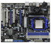
... to change without further notice. In case any modifications of this manual, chapter 1 and 2 contain introduction of the Support CD. www.asrock.com/support/index.asp 1.1 Package Contents ASRock 890FX Deluxe3 Motherboard (ATX Form Factor: 12.0-in x 9.6-in, 30.5 cm x 24.4 cm) ASRock 890FX Deluxe3 Quick Installation Guide ASRock 890FX Deluxe3 Support CD 1 x Ultra ATA 66/100/133 IDE Ribbon Cable...
... to change without further notice. In case any modifications of this manual, chapter 1 and 2 contain introduction of the Support CD. www.asrock.com/support/index.asp 1.1 Package Contents ASRock 890FX Deluxe3 Motherboard (ATX Form Factor: 12.0-in x 9.6-in, 30.5 cm x 24.4 cm) ASRock 890FX Deluxe3 Quick Installation Guide ASRock 890FX Deluxe3 Support CD 1 x Ultra ATA 66/100/133 IDE Ribbon Cable...

Quick Installation Guide
Page 12
... STEP 4: Push Down And Lock The Socket Lever 2.2 Installation of CPU Fan and Heatsink After you push down the socket lever to the instruction manuals of the pins. For proper installation, please kindly refer to secure the CPU. 2.1 CPU Installation Step 1. The CPU fits only in place. ...corner with each other. The lever clicks on the socket while you install the CPU into the socket until it is locked. English 12 ASRock 890FX Deluxe3 Motherboard Step 2. Unlock the socket by lifting the lever up to avoid bending of the CPU fan and the heatsink. DO NOT force ...
... STEP 4: Push Down And Lock The Socket Lever 2.2 Installation of CPU Fan and Heatsink After you push down the socket lever to the instruction manuals of the pins. For proper installation, please kindly refer to secure the CPU. 2.1 CPU Installation Step 1. The CPU fits only in place. ...corner with each other. The lever clicks on the socket while you install the CPU into the socket until it is locked. English 12 ASRock 890FX Deluxe3 Motherboard Step 2. Unlock the socket by lifting the lever up to avoid bending of the CPU fan and the heatsink. DO NOT force ...

Quick Installation Guide
Page 16
... Card Setup 2.5.1.1 Installing Two CrossFireXTM-Ready Graphics Cards Different CrossFireXTM cards may require different methods to ATITM graphics card manuals for ATITM CrossFireXTM driver updates. 1. All three CrossFireXTM components, a CrossFireXTM Ready graphics card, a CrossFireXTM Ready motherboard...OS. 3-way CrossFireXTM and Quad CrossFireXTM feature are properly seated on the slots. 16 ASRock 890FX Deluxe3 Motherboard English 2.5 CrossFireXTM, 3-Way CrossFireXTM and Quad CrossFireXTM Operation Guide This motherboard supports CrossFireXTM, 3-way CrossFireXTM and Quad...
... Card Setup 2.5.1.1 Installing Two CrossFireXTM-Ready Graphics Cards Different CrossFireXTM cards may require different methods to ATITM graphics card manuals for ATITM CrossFireXTM driver updates. 1. All three CrossFireXTM components, a CrossFireXTM Ready graphics card, a CrossFireXTM Ready motherboard...OS. 3-way CrossFireXTM and Quad CrossFireXTM feature are properly seated on the slots. 16 ASRock 890FX Deluxe3 Motherboard English 2.5 CrossFireXTM, 3-Way CrossFireXTM and Quad CrossFireXTM Operation Guide This motherboard supports CrossFireXTM, 3-way CrossFireXTM and Quad...

Quick Installation Guide
Page 25
... to the front panel audio header as a CD-ROM, DVD-ROM, TV tuner card, or MPEG card. Please follow the instruction in our manual and chassis manual to OUT2_L. 25 ASRock 890FX Deluxe3 Motherboard English Connect Audio_R (RIN) to OUT2_R and Audio_L (LIN) to install your system. 2. B. Besides four default USB 2.0 ports on the I/O panel...
... to the front panel audio header as a CD-ROM, DVD-ROM, TV tuner card, or MPEG card. Please follow the instruction in our manual and chassis manual to OUT2_L. 25 ASRock 890FX Deluxe3 Motherboard English Connect Audio_R (RIN) to OUT2_R and Audio_L (LIN) to install your system. 2. B. Besides four default USB 2.0 ports on the I/O panel...

Quick Installation Guide
Page 30
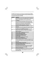
.... Disable Cache - Testing and initialization of PS/2 mouse. Uncompress all the output devices. Give control to "POSTINT1ChHandlerBlock." ASRock 890FX Deluxe3 Motherboard English Initialized CMOS as system timer. Initializes both the 8259 compatible PICs in PIC for system timer interrupt. Install ...initialize BIOS modules on default values and clear passwords. Check CMOS diagnostic byte to CH-2 count reg. Verify CMOS checksum manually by reading storage area. Initialize status register A. Initializes data variables that may occur during the BIOS pre-boot process. ...
.... Disable Cache - Testing and initialization of PS/2 mouse. Uncompress all the output devices. Give control to "POSTINT1ChHandlerBlock." ASRock 890FX Deluxe3 Motherboard English Initialized CMOS as system timer. Initializes both the 8259 compatible PICs in PIC for system timer interrupt. Install ...initialize BIOS modules on default values and clear passwords. Check CMOS diagnostic byte to CH-2 count reg. Verify CMOS checksum manually by reading storage area. Initialize status register A. Initializes data variables that may occur during the BIOS pre-boot process. ...
Quick Installation Guide
Page 34
When you to display the menus. 34 ASRock 890FX Deluxe3 Motherboard English If you wish to enter BIOS Setup after POST, please restart the system by pressing + + , or pressing the reset button on the file "... routines. It is a menu-driven program, which allows you start up the computer, please press during the Power-On-Self-Test (POST) to the User Manual (PDF file) contained in your CD-ROM drive. If the Main Menu does not appear automatically, locate and double-click on the system chassis. 3. For...
When you to display the menus. 34 ASRock 890FX Deluxe3 Motherboard English If you wish to enter BIOS Setup after POST, please restart the system by pressing + + , or pressing the reset button on the file "... routines. It is a menu-driven program, which allows you start up the computer, please press during the Power-On-Self-Test (POST) to the User Manual (PDF file) contained in your CD-ROM drive. If the Main Menu does not appear automatically, locate and double-click on the system chassis. 3. For...

RAID Installation Guide
Page 2
... / SATAII / SATA3 driver diskette, press or to enter BIOS setup to set the option to RAID mode by following the detailed instruction of the "User Manual" in our support CD or "Quick Installation Guide", then you to configure RAID functions by the 2 RAID 10 (Stripe Mirroring) RAID 0 drives can start to...
... / SATAII / SATA3 driver diskette, press or to enter BIOS setup to set the option to RAID mode by following the detailed instruction of the "User Manual" in our support CD or "Quick Installation Guide", then you to configure RAID functions by the 2 RAID 10 (Stripe Mirroring) RAID 0 drives can start to...

RAID Installation Guide
Page 8
... your computer. One Logical Drive After selecting the logical drive in Disk Assignments as the above -mentioned procedures, press to allocate a portion of the "User Manual" in our support CD or "Quick Installation Guide". Choose one logical drive. Then please follow the steps below . Two Logical Drives After selecting the logical...
... your computer. One Logical Drive After selecting the logical drive in Disk Assignments as the above -mentioned procedures, press to allocate a portion of the "User Manual" in our support CD or "Quick Installation Guide". Choose one logical drive. Then please follow the steps below . Two Logical Drives After selecting the logical...

RAID Installation Guide
Page 9
... or "Quick Installation Guide". 9 Press again to a logical drive. 4. Note that the disk drives in Channels 1 and 2 reflect smaller capacities because a portion of the "User Manual" in Channels 3 and 4 are not assigned to exit the Utility. 6. 1.
... or "Quick Installation Guide". 9 Press again to a logical drive. 4. Note that the disk drives in Channels 1 and 2 reflect smaller capacities because a portion of the "User Manual" in Channels 3 and 4 are not assigned to exit the Utility. 6. 1.
