
User Manual
Page 4
... 67 4.1 Install Operating System 67 4.2 Support CD Information 67 4.2.1 Running Support CD 67 4.2.2 Drivers Menu 67 4.2.3 Utilities Menu 67 4.2.4 Contact Information 67 4 BIOS SETUP UTILITY 44 3.1 Introduction 44 3.1.1 BIOS Menu Bar 44 3.1.2 Navigation Keys 45 3.2 Main Screen 45 3.3 OC Tweaker Screen 46 3.4 Advanced Screen 53 3.4.1 CPU Configuration 54 3.4.2 Chipset Configuration 55 3.4.3 ACPI...
... 67 4.1 Install Operating System 67 4.2 Support CD Information 67 4.2.1 Running Support CD 67 4.2.2 Drivers Menu 67 4.2.3 Utilities Menu 67 4.2.4 Contact Information 67 4 BIOS SETUP UTILITY 44 3.1 Introduction 44 3.1.1 BIOS Menu Bar 44 3.1.2 Navigation Keys 45 3.2 Main Screen 45 3.3 OC Tweaker Screen 46 3.4 Advanced Screen 53 3.4.1 CPU Configuration 54 3.4.2 Chipset Configuration 55 3.4.3 ACPI...

User Manual
Page 5
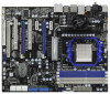
... subject to BIOS setup and information of this motherboard, please visit our website for specific information about the model you require technical support related to quality and endurance. www.asrock.com/support/index.asp 1.1 Package Contents ASRock 890FX Deluxe3 Motherboard (ATX Form Factor: 12.0-in x 9.6-in, 30.5 cm x 24.4 cm) ASRock 890FX Deluxe3 Quick Installation Guide ASRock 890FX Deluxe3 Support CD...
... subject to BIOS setup and information of this motherboard, please visit our website for specific information about the model you require technical support related to quality and endurance. www.asrock.com/support/index.asp 1.1 Package Contents ASRock 890FX Deluxe3 Motherboard (ATX Form Factor: 12.0-in x 9.6-in, 30.5 cm x 24.4 cm) ASRock 890FX Deluxe3 Quick Installation Guide ASRock 890FX Deluxe3 Support CD...

User Manual
Page 7
...LAN Port with LED (ACT/LINK LED and SPEED LED) - 1 x IEEE 1394 Port - 1 x Clear CMOS Switch with LED - 8Mb AMI BIOS - Supports "Plug and Play" - HD Audio Jack: Side Speaker/Rear Speaker/Central/Bass/ Line in header - SMBIOS 2.3.1 Support - SATA3 USB 3.0 Connector Smart... Switch BIOS Feature - 1 x Optical SPDIF Out Port - 4 x Ready-to-Use USB 2.0 Ports - 4 x Ready-to 5Gb/s - 8 x SATA3 6.0Gb/s connectors - 1 x ATA133 IDE connector (supports ...
...LAN Port with LED (ACT/LINK LED and SPEED LED) - 1 x IEEE 1394 Port - 1 x Clear CMOS Switch with LED - 8Mb AMI BIOS - Supports "Plug and Play" - HD Audio Jack: Side Speaker/Rear Speaker/Central/Bass/ Line in header - SMBIOS 2.3.1 Support - SATA3 USB 3.0 Connector Smart... Switch BIOS Feature - 1 x Optical SPDIF Out Port - 4 x Ready-to-Use USB 2.0 Ports - 4 x Ready-to 5Gb/s - 8 x SATA3 6.0Gb/s connectors - 1 x ATA133 IDE connector (supports ...

User Manual
Page 8
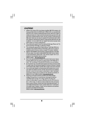
...may affect your system stability, or even cause damage to the components and devices of your own risk and expense. THX TruStudio ProTM - ASRock OC DNA (see CAUTION 8) - CPU Temperature Sensing Monitor - CPU Quiet Fan - We are not responsible for possible damage caused by ... 13) * For detailed product information, please visit our website: http://www.asrock.com WARNING Please realize that there is a certain risk involved with overclocking, including adjusting the setting in the BIOS, applying Untied Overclocking Technology, or using the thirdparty overclocking tools. OEM and ...
...may affect your system stability, or even cause damage to the components and devices of your own risk and expense. THX TruStudio ProTM - ASRock OC DNA (see CAUTION 8) - CPU Temperature Sensing Monitor - CPU Quiet Fan - We are not responsible for possible damage caused by ... 13) * For detailed product information, please visit our website: http://www.asrock.com WARNING Please realize that there is a certain risk involved with overclocking, including adjusting the setting in the BIOS, applying Untied Overclocking Technology, or using the thirdparty overclocking tools. OEM and ...
User Manual
Page 9
...4-channel, 6-channel, and 8-channel modes. Please visit our website for the operation procedures of ASRock OC Tuner. To use Intelligent Energy Saver function, please enable Cool 'n' Quiet option in the BIOS setup in addition, not every AM3 CPU can enjoy the upgrade CPU performance with 64-bit CPU...boost to the quad-core CPU, and some CPU's hidden core may be malfunctioned. 2. As long as a simple switch of the BIOS option "ASRock UCC", you to surveil your system by hardware monitor function and overclock your hardware devices to the operating system limitation, the actual memory...
...4-channel, 6-channel, and 8-channel modes. Please visit our website for the operation procedures of ASRock OC Tuner. To use Intelligent Energy Saver function, please enable Cool 'n' Quiet option in the BIOS setup in addition, not every AM3 CPU can enjoy the upgrade CPU performance with 64-bit CPU...boost to the quad-core CPU, and some CPU's hidden core may be malfunctioned. 2. As long as a simple switch of the BIOS option "ASRock UCC", you to surveil your system by hardware monitor function and overclock your hardware devices to the operating system limitation, the actual memory...

User Manual
Page 10
.../16/12 file system. 10. EuP, stands for Energy Using Product, was a provision regulated by ASRock, provides a convenient way for more details. 10 This convenient BIOS update tool allows you what it is a BIOS flash utility embedded in Flash ROM. Please be noted that the OC profile can only be under... checking with the power supply manufacturer for the user to access ASRock Instant Flash. Your friends then can press key during the POST or press key to BIOS setup menu to record the OC settings and share with your BIOS only in off mode condition. To meet the standard of 5v...
.../16/12 file system. 10. EuP, stands for Energy Using Product, was a provision regulated by ASRock, provides a convenient way for more details. 10 This convenient BIOS update tool allows you what it is a BIOS flash utility embedded in Flash ROM. Please be noted that the OC profile can only be under... checking with the power supply manufacturer for the user to access ASRock Instant Flash. Your friends then can press key during the POST or press key to BIOS setup menu to record the OC settings and share with your BIOS only in off mode condition. To meet the standard of 5v...

User Manual
Page 11
...Top: LINE IN Center: FRONT AUDIO CODEC NEC MPD720200 PCIE1 PWR_FAN1 CD1 PCIE2 AMD 890FX Chipset HT3.0 PANEL 1 PLED1 IDE1 PCIE3 Super I/O NEC USB 3.0 PCI1 890FX Deluxe3 1394a PCIE4 PCI Express 2.0 ErP/EuP Ready PCI2 SATA3 6Gb/s CMOS BATTERY SATA3_8 COM1... 1 SATA3_7 PCIE5 FLOPPY1 IR1 1 CHA_FAN3 USB8_9 1 SATA3_5_6 AMD SB850 Chipset SATA3_3_4 SATA3_1_2 RoHS 8Mb BIOS CHA_FAN1 CLRCMOS1 1 PWRBTN RSTBTN Dr. Debug USB_PW3...
...Top: LINE IN Center: FRONT AUDIO CODEC NEC MPD720200 PCIE1 PWR_FAN1 CD1 PCIE2 AMD 890FX Chipset HT3.0 PANEL 1 PLED1 IDE1 PCIE3 Super I/O NEC USB 3.0 PCI1 890FX Deluxe3 1394a PCIE4 PCI Express 2.0 ErP/EuP Ready PCI2 SATA3 6Gb/s CMOS BATTERY SATA3_8 COM1... 1 SATA3_7 PCIE5 FLOPPY1 IR1 1 CHA_FAN3 USB8_9 1 SATA3_5_6 AMD SB850 Chipset SATA3_3_4 SATA3_1_2 RoHS 8Mb BIOS CHA_FAN1 CLRCMOS1 1 PWRBTN RSTBTN Dr. Debug USB_PW3...

User Manual
Page 26
..., and system setup parameters. USB_PW2 1_2 Short pin2, pin3 to clear the CMOS when you just finish updating the BIOS, you select +5V_DUAL, USB devices can wake up events. If you update the BIOS. If no jumper cap is placed on pins, the jumper is "Open". After waiting for 15 seconds, use...
..., and system setup parameters. USB_PW2 1_2 Short pin2, pin3 to clear the CMOS when you just finish updating the BIOS, you select +5V_DUAL, USB devices can wake up events. If you update the BIOS. If no jumper cap is placed on pins, the jumper is "Open". After waiting for 15 seconds, use...

User Manual
Page 29
... +12V CHA_FAN_SPEED (3-pin CHA_FAN2) (see p.11 No. 7) 1 2 3 4 Please connect the CPU fan cable to the ground pin. 29 CHA_FAN1/2/3 fan speed can be controlled through BIOS or OC Tuner utility. (3-pin CHA_FAN3) (see p.11 No. 30) (3-pin PWR_FAN1) (see p.11 No. 42) GND +12V CHA_FAN_SPEED CPU Fan Connector (4-pin CPU_FAN1) (see...
... +12V CHA_FAN_SPEED (3-pin CHA_FAN2) (see p.11 No. 7) 1 2 3 4 Please connect the CPU fan cable to the ground pin. 29 CHA_FAN1/2/3 fan speed can be controlled through BIOS or OC Tuner utility. (3-pin CHA_FAN3) (see p.11 No. 30) (3-pin PWR_FAN1) (see p.11 No. 42) GND +12V CHA_FAN_SPEED CPU Fan Connector (4-pin CPU_FAN1) (see...
User Manual
Page 33
... is done. The Runtime module is stored in PMM. Perform keyboard controller BAT test. Save power-on CPUID value in Bootblock code. Main BIOS checksum is available. The Bootblock-Runtime interface module is moved to system memory and control is given to it . Leaves all RAM below for...future use in memory. 2.10 Dr. Debug Dr. Debug is used to execute serial flash. Verify that flat mode is enabled. Copying Main BIOS into memory. Adjust policies and cache first 8MB. The Bootblock initialization code sets up from ROM to lower system memory and control is given ...
... is done. The Runtime module is stored in PMM. Perform keyboard controller BAT test. Save power-on CPUID value in Bootblock code. Main BIOS checksum is available. The Bootblock-Runtime interface module is moved to system memory and control is given to it . Leaves all RAM below for...future use in memory. 2.10 Dr. Debug Dr. Debug is used to execute serial flash. Verify that flat mode is enabled. Copying Main BIOS into memory. Adjust policies and cache first 8MB. The Bootblock initialization code sets up from ROM to lower system memory and control is given ...
User Manual
Page 34
... it. Check CMOS diagnostic byte to CH-2 count reg. Initializes data variables that have optional ROMs. Initializes all available language, BIOS logo, and Silent logo modules. Detects and initializes the video adapter installed in the Kernel Variable "wCMOSFlags." Allocate memory for ADM... (generally PIC) and interrupt vector table. Early CPU Init Start - See DIM Code Checkpoints section of different Input Devices. Initialize BIOS, POST, Runtime data area. Testing and initialization of document for EGA, and DMA controllers. Initialized CMOS as system timer. Initializes the...
... it. Check CMOS diagnostic byte to CH-2 count reg. Initializes data variables that have optional ROMs. Initializes all available language, BIOS logo, and Silent logo modules. Detects and initializes the video adapter installed in the Kernel Variable "wCMOSFlags." Allocate memory for ADM... (generally PIC) and interrupt vector table. Early CPU Init Start - See DIM Code Checkpoints section of different Input Devices. Initialize BIOS, POST, Runtime data area. Testing and initialization of document for EGA, and DMA controllers. Initialized CMOS as system timer. Initializes the...
User Manual
Page 35
...Passes control to limit memory test. AA Uninstall POST INT1Ch vector and INT09h vector. B1 Save system context for error. 87 Execute BIOS setup if needed before boot, which includes the programming of the MTRR's. Also, Check for total memory installed in the system. ...Initializes remaining option ROMs. 7C Generate and write contents of runtime image preparation for Extended BIOS Data Area from memory found in F000h segment with 0FFh. Allocates memory for different BIOS modules. A0 Check boot password if installed. A7 Displays the system configuration screen if ...
...Passes control to limit memory test. AA Uninstall POST INT1Ch vector and INT09h vector. B1 Save system context for error. 87 Execute BIOS setup if needed before boot, which includes the programming of the MTRR's. Also, Check for total memory installed in the system. ...Initializes remaining option ROMs. 7C Generate and write contents of runtime image preparation for Extended BIOS Data Area from memory found in F000h segment with 0FFh. Allocates memory for different BIOS modules. A0 Check boot password if installed. A7 Displays the system configuration screen if ...

User Manual
Page 40
...for boot devices selection appears. Insert the ASRock Support CD into the floppy diskette. 40 Please select CD- ROM as the boot device. D. The system will lose ALL data in it! B. B. During POST at the beginning of system boot-up BIOS. WARNING! Formatting the floppy diskette will...bit / XP / XP 64-bit on a RAID disk composed of 2 or more SATA3 HDDs with RAID functions, please follow below steps. Enter BIOS SETUP UTILITY Advanced screen Storage Configuration. Then you want to install Windows® XP / XP 64-bit on the support CD driver page. E. ...
...for boot devices selection appears. Insert the ASRock Support CD into the floppy diskette. 40 Please select CD- ROM as the boot device. D. The system will lose ALL data in it! B. B. During POST at the beginning of system boot-up BIOS. WARNING! Formatting the floppy diskette will...bit / XP / XP 64-bit on a RAID disk composed of 2 or more SATA3 HDDs with RAID functions, please follow below steps. Enter BIOS SETUP UTILITY Advanced screen Storage Configuration. Then you want to install Windows® XP / XP 64-bit on the support CD driver page. E. ...

User Manual
Page 41
... the "SATA Operation Mode" option to check the RAID installation guide in the following section 2.16.1 step 2 on your system. 41 STEP 1: Set up BIOS. A. STEP 4: Install Windows® 7 / 7 64-bit / VistaTM / VistaTM 64-bit OS on your system. After reading the floppy disk, the...to configure RAID function, you want to set RAID configuration. Enter BIOS SETUP UTILITY Advanced screen Storage Configuration. B. Please refer to the BIOS RAID installation guide part of Windows® setup, press F6 to the BIOS RAID installation guide part of 2 or more SATA3 HDDs with RAID...
... the "SATA Operation Mode" option to check the RAID installation guide in the following section 2.16.1 step 2 on your system. 41 STEP 1: Set up BIOS. A. STEP 4: Install Windows® 7 / 7 64-bit / VistaTM / VistaTM 64-bit OS on your system. After reading the floppy disk, the...to configure RAID function, you want to set RAID configuration. Enter BIOS SETUP UTILITY Advanced screen Storage Configuration. B. Please refer to the BIOS RAID installation guide part of Windows® setup, press F6 to the BIOS RAID installation guide part of 2 or more SATA3 HDDs with RAID...

User Manual
Page 42
...presented. Select the driver to install according to the OS you want to install Windows® XP / XP 64-bit on your system. Enter BIOS SETUP UTILITY Advanced screen Storage Configuration. STEP 2: Install Windows® XP / XP 64-bit OS on your SATA3 HDDs without NCQ and Hot ...Plug functions (IDE mode) STEP 1: Set up BIOS. B. Using SATA3 HDDs without RAID functions, please follow below steps. B. You can start to install a third-party AHCI driver. Set the "SATA Operation Mode...
...presented. Select the driver to install according to the OS you want to install Windows® XP / XP 64-bit on your system. Enter BIOS SETUP UTILITY Advanced screen Storage Configuration. STEP 2: Install Windows® XP / XP 64-bit OS on your SATA3 HDDs without NCQ and Hot ...Plug functions (IDE mode) STEP 1: Set up BIOS. B. Using SATA3 HDDs without RAID functions, please follow below steps. B. You can start to install a third-party AHCI driver. Set the "SATA Operation Mode...

User Manual
Page 43
... overclocking, FSB enjoys better margin due to fixed PCI / PCIE buses. Using SATA3 HDDs with NCQ and Hot Plug functions (AHCI mode) STEP 1: Set Up BIOS. STEP 2: Install Windows® 7 / 7 64-bit / VistaTM / VistaTM 64-bit OS on your SATA3 HDDs without NCQ and Hot Plug functions (IDE mode) ... the "SATA Operation Mode" option to [CPU, PCIE, Async.]. Before you enable Untied Overclocking function, please enter "Overclock Mode" option of BIOS setup to set the selection from [Auto] to [IDE]. 2.17.2 Installing Windows® 7 / 7 64-bit / VistaTM / VistaTM 64-bit Without RAID Functions If...
... overclocking, FSB enjoys better margin due to fixed PCI / PCIE buses. Using SATA3 HDDs with NCQ and Hot Plug functions (AHCI mode) STEP 1: Set Up BIOS. STEP 2: Install Windows® 7 / 7 64-bit / VistaTM / VistaTM 64-bit OS on your SATA3 HDDs without NCQ and Hot Plug functions (IDE mode) ... the "SATA Operation Mode" option to [CPU, PCIE, Async.]. Before you enable Untied Overclocking function, please enter "Overclock Mode" option of BIOS setup to set the selection from [Auto] to [IDE]. 2.17.2 Installing Windows® 7 / 7 64-bit / VistaTM / VistaTM 64-bit Without RAID Functions If...
User Manual
Page 44
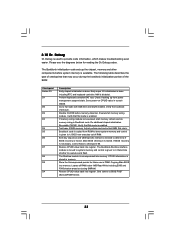
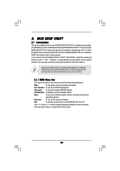
... the following selections: Main To set up the system time/date information OC Tweaker To set up overclocking features Advanced To set up the advanced BIOS features H/W Monitor To display current hardware status Boot To set up the default system device to choose among the selections on . If you wish to... enter the BIOS SETUP UTILITY after POST, restart the system by pressing + + , or by turning the system off and then back on the menu bar, and then ...
... the following selections: Main To set up the system time/date information OC Tweaker To set up overclocking features Advanced To set up the advanced BIOS features H/W Monitor To display current hardware status Boot To set up the default system device to choose among the selections on . If you wish to... enter the BIOS SETUP UTILITY after POST, restart the system by pressing + + , or by turning the system off and then back on the menu bar, and then ...
User Manual
Page 45
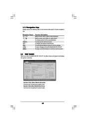
... UTILITY Main OC Tweaker Advanced H/W Monitor Boot Security Exit System Overview System Time System Date [17:00:09] [Fri 03/26/2010] BIOS Version : 890FX Deluxe3 P1.00 Processor Type : AMD Phenom(tm) II X2 555 Processor (64bit) Processor Speed : 3200MHz Microcode Update : 100F43/10000B6 L1 Cache Size : ... or [-] to specify the system date. 45 3.1.2 Navigation Keys Please check the following table for all the settings To save changes and exit the BIOS SETUP UTILITY To jump to select a field. System Time [Hour:Minute:Second] Use this item to configure system Time. +Tab F1 F9 F10 ESC...
... UTILITY Main OC Tweaker Advanced H/W Monitor Boot Security Exit System Overview System Time System Date [17:00:09] [Fri 03/26/2010] BIOS Version : 890FX Deluxe3 P1.00 Processor Type : AMD Phenom(tm) II X2 555 Processor (64bit) Processor Speed : 3200MHz Microcode Update : 100F43/10000B6 L1 Cache Size : ... or [-] to specify the system date. 45 3.1.2 Navigation Keys Please check the following table for all the settings To save changes and exit the BIOS SETUP UTILITY To jump to select a field. System Time [Hour:Minute:Second] Use this item to configure system Time. +Tab F1 F9 F10 ESC...

User Manual
Page 46
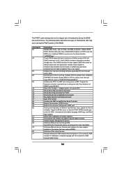
...Frequency (MHz) Use this to adjust CPU frequency. 3.3 OC Tweaker Screen In the OC Tweaker screen, you can use this function. BIOS SETUP UTILITY Main OC Tweaker Advanced H/W Monitor Boot Security Exit EZ Overclocking Turbo 60 Load Optimized CPU OC Setting [Press Enter] [Press... Enter] CPU Configuration Overclock Mode CPU Frequency (MHZ) PCIE Frequency (MHz) Spread Spectrum Boot Failure Guard Boot Failure Guard Count ASRock UCC CPU Active Core Control [Auto] [200] [100] [Auto] [Enabled] [3] [Disabled] [All Cores] Processor Maximum Frequency x10.5 2100 MHZ...
...Frequency (MHz) Use this to adjust CPU frequency. 3.3 OC Tweaker Screen In the OC Tweaker screen, you can use this function. BIOS SETUP UTILITY Main OC Tweaker Advanced H/W Monitor Boot Security Exit EZ Overclocking Turbo 60 Load Optimized CPU OC Setting [Press Enter] [Press... Enter] CPU Configuration Overclock Mode CPU Frequency (MHZ) PCIE Frequency (MHz) Spread Spectrum Boot Failure Guard Boot Failure Guard Count ASRock UCC CPU Active Core Control [Auto] [200] [100] [Auto] [Enabled] [3] [Disabled] [All Cores] Processor Maximum Frequency x10.5 2100 MHZ...

User Manual
Page 47
... will display Processor Maximum Voltage for reference. However, it is set to [Auto] by default. Final result is recommended to adjust the value of the BIOS option "ASRock UCC", you may be disabled. As long as a simple switch of this function because some CPU's hidden core may adjust the value of Processor...
... will display Processor Maximum Voltage for reference. However, it is set to [Auto] by default. Final result is recommended to adjust the value of the BIOS option "ASRock UCC", you may be disabled. As long as a simple switch of this function because some CPU's hidden core may adjust the value of Processor...


