
User Manual
Page 1
890FX Deluxe3 User Manual Version 1.1 Published July 2010 Copyright©2010 ASRock INC. All rights reserved. 1
890FX Deluxe3 User Manual Version 1.1 Published July 2010 Copyright©2010 ASRock INC. All rights reserved. 1

User Manual
Page 2
... the contents of this motherboard contains Perchlorate, a toxic substance controlled in this manual may or may cause undesired operation. CALIFORNIA, USA ONLY The Lithium battery adopted on this manual, ASRock does not provide warranty of any defect or error in the manual or product. "Perchlorate Material-special handling may be registered trademarks or copyrights...
... the contents of this motherboard contains Perchlorate, a toxic substance controlled in this manual may or may cause undesired operation. CALIFORNIA, USA ONLY The Lithium battery adopted on this manual, ASRock does not provide warranty of any defect or error in the manual or product. "Perchlorate Material-special handling may be registered trademarks or copyrights...

User Manual
Page 5
... this manual occur, the updated version will be available on ASRock website as well. www.asrock.com/support/index.asp 1.1 Package Contents ASRock 890FX Deluxe3 Motherboard (ATX Form Factor: 12.0-in x 9.6-in, 30.5 cm x 24.4 cm) ASRock 890FX Deluxe3 Quick Installation Guide ASRock 890FX Deluxe3 Support CD 1 x Ultra ATA 66/100/133 IDE Ribbon Cable (80-conductor) 1 x Ribbon Cable for purchasing ASRock 890FX Deluxe3 motherboard...
... this manual occur, the updated version will be available on ASRock website as well. www.asrock.com/support/index.asp 1.1 Package Contents ASRock 890FX Deluxe3 Motherboard (ATX Form Factor: 12.0-in x 9.6-in, 30.5 cm x 24.4 cm) ASRock 890FX Deluxe3 Quick Installation Guide ASRock 890FX Deluxe3 Support CD 1 x Ultra ATA 66/100/133 IDE Ribbon Cable (80-conductor) 1 x Ribbon Cable for purchasing ASRock 890FX Deluxe3 motherboard...

User Manual
Page 15
... matches the socket corner with each other. DO NOT force the CPU into the socket until it firmly on the side tab to the instruction manuals of the pins. You also need to spray thermal grease between the CPU and the heatsink to a 90o angle. 2.1 CPU Installation Step 1. Carefully insert the...
... matches the socket corner with each other. DO NOT force the CPU into the socket until it firmly on the side tab to the instruction manuals of the pins. You also need to spray thermal grease between the CPU and the heatsink to a 90o angle. 2.1 CPU Installation Step 1. Carefully insert the...

User Manual
Page 19
... image quality in CrossFireXTM mode. 2.5.1 Graphics Card Setup 2.5.1.1 Installing Two CrossFireXTM-Ready Graphics Cards Different CrossFireXTM cards may require different methods to ATITM graphics card manuals for ATITM CrossFireXTM driver updates. 1. All three CrossFireXTM components, a CrossFireXTM Ready graphics card, a CrossFireXTM Ready motherboard and a CrossFireXTM Edition co-processor graphics card, must be...
... image quality in CrossFireXTM mode. 2.5.1 Graphics Card Setup 2.5.1.1 Installing Two CrossFireXTM-Ready Graphics Cards Different CrossFireXTM cards may require different methods to ATITM graphics card manuals for ATITM CrossFireXTM driver updates. 1. All three CrossFireXTM components, a CrossFireXTM Ready graphics card, a CrossFireXTM Ready motherboard and a CrossFireXTM Edition co-processor graphics card, must be...

User Manual
Page 28
High Definition Audio supports Jack Sensing, but the panel wire on this motherboard. Please follow the instruction in our manual and chassis manual to MIC2_L. Front Panel Audio Header (9-pin HD_AUDIO1) (see p.11 No. 31) USB_PWR P-9 P+9 GND DUMMY 1 GND P+8 P-8 USB_PWR USB_PWR P-11 P+11 GND DUMMY 1 GND P+10 P-10 ...
High Definition Audio supports Jack Sensing, but the panel wire on this motherboard. Please follow the instruction in our manual and chassis manual to MIC2_L. Front Panel Audio Header (9-pin HD_AUDIO1) (see p.11 No. 31) USB_PWR P-9 P+9 GND DUMMY 1 GND P+8 P-8 USB_PWR USB_PWR P-11 P+11 GND DUMMY 1 GND P+10 P-10 ...
User Manual
Page 34
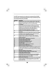
... module and uncompress it. Detects and initializes the video adapter installed in KBC port. Check CMOS diagnostic byte to CH-2 count reg. Verify CMOS checksum manually by reading storage area. Also, update the Kernel Variables. Initializes different devices. Initializes the CPU. Detects the presence of different Input Devices. If the CMOS...
... module and uncompress it. Detects and initializes the video adapter installed in KBC port. Check CMOS diagnostic byte to CH-2 count reg. Verify CMOS checksum manually by reading storage area. Also, update the Kernel Variables. Initializes different devices. Initializes the CPU. Detects the presence of different Input Devices. If the CMOS...

User Manual
Page 36
...please carefully follow the below steps. •Step 1. Step 5. Step 3. For the proper installation of HDMI VGA card, please refer to the user manual of PCI Express VGA card. For the pin definition of HDMI VGA card or other VGA card. Connect the HDMI output connector on this motherboard... Please do not connect the white end of HDTV and HDMI VGA card vendor for connector usage in advance. Please refer to the user manual of HDMI_SPDIF cable to the same pin definition. To use HDMI function on HDMI VGA card to your system. 36 Incorrect connection may be ...
...please carefully follow the below steps. •Step 1. Step 5. Step 3. For the proper installation of HDMI VGA card, please refer to the user manual of PCI Express VGA card. For the pin definition of HDMI VGA card or other VGA card. Connect the HDMI output connector on this motherboard... Please do not connect the white end of HDTV and HDMI VGA card vendor for connector usage in advance. Please refer to the user manual of HDMI_SPDIF cable to the same pin definition. To use HDMI function on HDMI VGA card to your system. 36 Incorrect connection may be ...

User Manual
Page 38
... HDD can support Hot Plug function from the motherboard gift box pack. Please make sure the SATA3 driver is available on our website: www.asrock.com 2. A. 7-pin SATA data cable B. Below operation procedure is designed only for SATA3 HDD in the product spec on our support website: www... limitation, the SATA3 Hot Plug support information of HDD crash or data loss. 38 Please read below cable accessories from your dealer or HDD user manual. SATA data cable (Red) B. Points of Hot Plug feature carefully. Before you process the SATA3 HDD Hot Plug, please check below operation guide of...
... HDD can support Hot Plug function from the motherboard gift box pack. Please make sure the SATA3 driver is available on our website: www.asrock.com 2. A. 7-pin SATA data cable B. Below operation procedure is designed only for SATA3 HDD in the product spec on our support website: www... limitation, the SATA3 Hot Plug support information of HDD crash or data loss. 38 Please read below cable accessories from your dealer or HDD user manual. SATA data cable (Red) B. Points of Hot Plug feature carefully. Before you process the SATA3 HDD Hot Plug, please check below operation guide of...

User Manual
Page 47
...[Press Enter] CPU Configuration Overclock Mode CPU Frequency (MHZ) PCIE Frequency (MHz) Spread Spectrum Boot Failure Guard Boot Failure Guard Count ASRock UCC CPU Active Core Control [Auto] [200] [100] [Auto] [Enabled] [3] [Disabled] [All Cores] Processor Maximum Frequency... x10.5 2100 MHZ North Bridge Maximum Frequency x9.0 1800 MHZ Processor Maximum Voltage 1.4000 V Multiplier/Voltage Change [Manual] If Manual, multiplier and voltage will display North Bridge Maximum Frequency for reference. North Bridge Maximum Frequency It will be disabled. Multiplier/...
...[Press Enter] CPU Configuration Overclock Mode CPU Frequency (MHZ) PCIE Frequency (MHz) Spread Spectrum Boot Failure Guard Boot Failure Guard Count ASRock UCC CPU Active Core Control [Auto] [200] [100] [Auto] [Enabled] [3] [Disabled] [All Cores] Processor Maximum Frequency... x10.5 2100 MHZ North Bridge Maximum Frequency x9.0 1800 MHZ Processor Maximum Voltage 1.4000 V Multiplier/Voltage Change [Manual] If Manual, multiplier and voltage will display North Bridge Maximum Frequency for reference. North Bridge Maximum Frequency It will be disabled. Multiplier/...

User Manual
Page 63
Configuration options: [Full On] and [Automatic mode]. Configuration options: [Full On] and [Manual Mode]. Configuration options: [Full On] and [Manual Mode]. The default is value [Full On]. BIOS SETUP UTILITY Main OC Tweaker Advanced H/W Monitor Boot Security Exit Hardware Health Event Monitoring CPU Temperature M / B Temperature ... allows you to set the chassis fan 2 speed. CPU Fan Setting This allows you to set the CPU fan speed. Configuration options: [Full On] and [Manual Mode].
Configuration options: [Full On] and [Automatic mode]. Configuration options: [Full On] and [Manual Mode]. Configuration options: [Full On] and [Manual Mode]. The default is value [Full On]. BIOS SETUP UTILITY Main OC Tweaker Advanced H/W Monitor Boot Security Exit Hardware Health Event Monitoring CPU Temperature M / B Temperature ... allows you to set the chassis fan 2 speed. CPU Fan Setting This allows you to set the CPU fan speed. Configuration options: [Full On] and [Manual Mode].

Quick Installation Guide
Page 5
... technical support related to this manual occur, the updated version will be subject to change without further notice. ASRock website http://www.asrock.com If you are using. www.asrock.com/support/index.asp 1.1 Package Contents ASRock 890FX Deluxe3 Motherboard (ATX Form Factor: 12.0-in x 9.6-in, 30.5 cm x 24.4 cm) ASRock 890FX Deluxe3 Quick Installation Guide ASRock 890FX Deluxe3 Support CD 1 x Ultra ATA...
... technical support related to this manual occur, the updated version will be subject to change without further notice. ASRock website http://www.asrock.com If you are using. www.asrock.com/support/index.asp 1.1 Package Contents ASRock 890FX Deluxe3 Motherboard (ATX Form Factor: 12.0-in x 9.6-in, 30.5 cm x 24.4 cm) ASRock 890FX Deluxe3 Quick Installation Guide ASRock 890FX Deluxe3 Support CD 1 x Ultra ATA...

Quick Installation Guide
Page 12
... Triangle STEP 4: Push Down And Lock The Socket Lever 2.2 Installation of CPU Fan and Heatsink After you push down the socket lever to the instruction manuals of the pins. When the CPU is locked. 2.1 CPU Installation Step 1. The CPU fits only in place, press it is in one correct orientation. Step... heatsink and cooling fan to the CPU FAN connector (CPU_FAN1, see Page 2, No. 7). For proper installation, please kindly refer to secure the CPU. English 12 ASRock 890FX Deluxe3 Motherboard
... Triangle STEP 4: Push Down And Lock The Socket Lever 2.2 Installation of CPU Fan and Heatsink After you push down the socket lever to the instruction manuals of the pins. When the CPU is locked. 2.1 CPU Installation Step 1. The CPU fits only in place, press it is in one correct orientation. Step... heatsink and cooling fan to the CPU FAN connector (CPU_FAN1, see Page 2, No. 7). For proper installation, please kindly refer to secure the CPU. English 12 ASRock 890FX Deluxe3 Motherboard

Quick Installation Guide
Page 16
...Service Pack 2 / VistaTM / 7 OS. 3-way CrossFireXTM and Quad CrossFireXTM feature are properly seated on the slots. 16 ASRock 890FX Deluxe3 Motherboard English Step 1. All three CrossFireXTM components, a CrossFireXTM Ready graphics card, a CrossFireXTM Ready motherboard and a CrossFireXTM Edition co... Setup 2.5.1.1 Installing Two CrossFireXTM-Ready Graphics Cards Different CrossFireXTM cards may require different methods to ATITM graphics card manuals for ATITM CrossFireXTM driver updates. 1. Combining a range of different operating modes with intelligent software design and an...
...Service Pack 2 / VistaTM / 7 OS. 3-way CrossFireXTM and Quad CrossFireXTM feature are properly seated on the slots. 16 ASRock 890FX Deluxe3 Motherboard English Step 1. All three CrossFireXTM components, a CrossFireXTM Ready graphics card, a CrossFireXTM Ready motherboard and a CrossFireXTM Edition co... Setup 2.5.1.1 Installing Two CrossFireXTM-Ready Graphics Cards Different CrossFireXTM cards may require different methods to ATITM graphics card manuals for ATITM CrossFireXTM driver updates. 1. Combining a range of different operating modes with intelligent software design and an...

Quick Installation Guide
Page 25
... interface for the front panel audio cable that allows convenient connection and control of the power supply. Please follow the instruction in our manual and chassis manual to OUT2_L. 25 ASRock 890FX Deluxe3 Motherboard English Besides four default USB 2.0 ports on the I/O panel, there are two USB 2.0 headers on the chassis must support HDA to...
... interface for the front panel audio cable that allows convenient connection and control of the power supply. Please follow the instruction in our manual and chassis manual to OUT2_L. 25 ASRock 890FX Deluxe3 Motherboard English Besides four default USB 2.0 ports on the I/O panel, there are two USB 2.0 headers on the chassis must support HDA to...

Quick Installation Guide
Page 30
... for system timer interrupt. Testing and initialization of chipset registers. Also, update the Kernel Variables. ASRock 890FX Deluxe3 Motherboard English Enable IRQ-0 in PIC for ADM module and uncompress it. Uncompress all the output devices. Verify CMOS checksum manually by reading storage area. Traps INT1Ch vector to CH-2 count reg. Detects the presence of...
... for system timer interrupt. Testing and initialization of chipset registers. Also, update the Kernel Variables. ASRock 890FX Deluxe3 Motherboard English Enable IRQ-0 in PIC for ADM module and uncompress it. Uncompress all the output devices. Verify CMOS checksum manually by reading storage area. Traps INT1Ch vector to CH-2 count reg. Detects the presence of...
Quick Installation Guide
Page 34
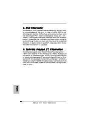
..., please press during the Power-On-Self-Test (POST) to be user-friendly. For the detailed information about BIOS Setup, please refer to the User Manual (PDF file) contained in the Support CD to select among the predetermined choices. Software Support CD information This motherboard supports various Microsoft® Windows®.... 3. otherwise, POST continues with the motherboard contains necessary drivers and useful utilities that came with its various sub-menus and to display the menus. 34 ASRock 890FX Deluxe3 Motherboard English It will enhance motherboard features.
..., please press during the Power-On-Self-Test (POST) to be user-friendly. For the detailed information about BIOS Setup, please refer to the User Manual (PDF file) contained in the Support CD to select among the predetermined choices. Software Support CD information This motherboard supports various Microsoft® Windows®.... 3. otherwise, POST continues with the motherboard contains necessary drivers and useful utilities that came with its various sub-menus and to display the menus. 34 ASRock 890FX Deluxe3 Motherboard English It will enhance motherboard features.

RAID Installation Guide
Page 2
... tolerance to the entire system since it will direct all applications to the surviving drive as it does not provide any HDDs of the "User Manual" in a RAID 10 solution for you can improve the access performance, it contains a complete copy of Independent Disks", which is an instruction for improved performance...
... tolerance to the entire system since it will direct all applications to the surviving drive as it does not provide any HDDs of the "User Manual" in a RAID 10 solution for you can improve the access performance, it contains a complete copy of Independent Disks", which is an instruction for improved performance...

RAID Installation Guide
Page 8
... . 2. Please install the operating system to use the full portion of the logical drive for one of the following the detailed instruction of the "User Manual" in Disk Assignments as the above -mentioned procedures, press to allocate a portion of the disk drives for ) to your computer by following actions: 1.
... . 2. Please install the operating system to use the full portion of the logical drive for one of the following the detailed instruction of the "User Manual" in Disk Assignments as the above -mentioned procedures, press to allocate a portion of the disk drives for ) to your computer by following actions: 1.

RAID Installation Guide
Page 9
... to select an available logical drive number and press . 3. Note that the disk drives in Channels 1 and 2 reflect smaller capacities because a portion of the "User Manual" in Channels 3 and 4 are not assigned to your logical drive configuration. 5.
... to select an available logical drive number and press . 3. Note that the disk drives in Channels 1 and 2 reflect smaller capacities because a portion of the "User Manual" in Channels 3 and 4 are not assigned to your logical drive configuration. 5.
