
User Manual
Page 1
775VM8 User Manual Version 1.0 Published April 2005 Copyright©2005 ASRock INC. All rights reserved. 1
775VM8 User Manual Version 1.0 Published April 2005 Copyright©2005 ASRock INC. All rights reserved. 1

User Manual
Page 2
...intent to infringe. Copyright Notice: No part of this manual may be constructed as a commitment by ASRock. This device complies with Part 15 of any defect or error in this manual, ASRock does not provide warranty of the FCC Rules. With respect to the contents of this manual may ...or consequential damages (including damages for loss of profits, loss of business, loss of data, interruption of business and the like), even if ASRock has been advised of the possibility of such damages arising from any kind, either expressed or implied, including but not limited to change without written...
...intent to infringe. Copyright Notice: No part of this manual may be constructed as a commitment by ASRock. This device complies with Part 15 of any defect or error in this manual, ASRock does not provide warranty of the FCC Rules. With respect to the contents of this manual may ...or consequential damages (including damages for loss of profits, loss of business, loss of data, interruption of business and the like), even if ASRock has been advised of the possibility of such damages arising from any kind, either expressed or implied, including but not limited to change without written...

User Manual
Page 3
... With RAID Functions 22 2.12 Installing Windows 98 / ME / 2000 / XP / XP 64-bit Without RAID Functions 22 3. Contents 1. Introduction 5 1.1 Package Contents 5 1.2 Specifications 6 1.3 Motherboard Layout 8 1.4 ASRock I/O Plus 9 TM 2.
... With RAID Functions 22 2.12 Installing Windows 98 / ME / 2000 / XP / XP 64-bit Without RAID Functions 22 3. Contents 1. Introduction 5 1.1 Package Contents 5 1.2 Specifications 6 1.3 Motherboard Layout 8 1.4 ASRock I/O Plus 9 TM 2.

User Manual
Page 4
Software Support 38 4.1 Install Operating System 38 4.2 Support CD Information 38 4.2.1 Running Support CD 38 4.2.2 Drivers Menu 38 4.2.3 Utilities Menu 38 4.2.4 "LGA 775 CPU Installation Live Demo" Program.... 38 4.2.5 Contact Information 38 4 3.4 Hardware Health Event Monitoring Screen 34 3.5 Boot Screen 34 3.5.1 Boot Settings Configuration 35 3.5.2 Boot Device Priority 35 3.6 Security Screen 36 3.7 Exit Screen 37 4.
Software Support 38 4.1 Install Operating System 38 4.2 Support CD Information 38 4.2.1 Running Support CD 38 4.2.2 Drivers Menu 38 4.2.3 Utilities Menu 38 4.2.4 "LGA 775 CPU Installation Live Demo" Program.... 38 4.2.5 Contact Information 38 4 3.4 Hardware Health Event Monitoring Screen 34 3.5 Boot Screen 34 3.5.1 Boot Settings Configuration 35 3.5.2 Boot Device Priority 35 3.6 Security Screen 36 3.7 Exit Screen 37 4.
User Manual
Page 5
...66/100/133 IDE Ribbon Cable One Ribbon Cable for purchasing ASRock 775VM8 motherboard, a reliable motherboard produced under ASRock's consistently stringent quality control. It delivers excellent performance with robust design conforming to ASRock's commitment to BIOS setup and information of the Support CD...software might be updated, the content of the motherboard and step-bystep guide to change without further notice. ASRock website http://www.asrock.com 1.1 Package Contents ASRock 775VM8 Motherboard (Micro ATX Form Factor: 9.6-in x 8.2-in Floppy Drive One Serial ATA (SATA) Cable One...
...66/100/133 IDE Ribbon Cable One Ribbon Cable for purchasing ASRock 775VM8 motherboard, a reliable motherboard produced under ASRock's consistently stringent quality control. It delivers excellent performance with robust design conforming to ASRock's commitment to BIOS setup and information of the Support CD...software might be updated, the content of the motherboard and step-bystep guide to change without further notice. ASRock website http://www.asrock.com 1.1 Package Contents ASRock 775VM8 Motherboard (Micro ATX Form Factor: 9.6-in x 8.2-in Floppy Drive One Serial ATA (SATA) Cable One...

User Manual
Page 6
...802.3u (10/100 Ethernet), supports Wake-On-LAN Hardware Monitor: CPU temperature sensing Chassis temperature sensing CPU overheat shutdown to protect CPU life (ASRock U-COP)(see CAUTION 2) CPU fan tachometer Chassis fan tachometer Voltage monitoring: +12V, +5V, +3.3V, Vcore PCI slots: 3 slots with ...Specification 2.2, PCI3 slot shared with AMR AGP slot: 1 AGP slot, supports 1.5V, 8X/4X AGP card (see CAUTION 3) AMR slot: 1 slot, supports ASRock MR card USB 2.0: 8 USB 2.0 ports: include 6 ready-to-use USB 2.0 ports on the rear panel, plus two on-board headers supporting 2 extra ...
...802.3u (10/100 Ethernet), supports Wake-On-LAN Hardware Monitor: CPU temperature sensing Chassis temperature sensing CPU overheat shutdown to protect CPU life (ASRock U-COP)(see CAUTION 2) CPU fan tachometer Chassis fan tachometer Voltage monitoring: +12V, +5V, +3.3V, Vcore PCI slots: 3 slots with ...Specification 2.2, PCI3 slot shared with AMR AGP slot: 1 AGP slot, supports 1.5V, 8X/4X AGP card (see CAUTION 3) AMR slot: 1 slot, supports ASRock MR card USB 2.0: 8 USB 2.0 ports: include 6 ready-to-use USB 2.0 ports on the rear panel, plus two on-board headers supporting 2 extra ...
User Manual
Page 7
... offers stepless control, it back again. Power Management for advanced users' reference, see CAUTION 5) OS: Microsoft® Windows® 98SE / ME / 2000 / XP compliant CAUTION! 1. ASRock I/O PlusTM: 1 PS/2 mouse port, 1 PS/2 keyboard port, 1 VGA port, 1 parallel port: ECP/EPP support, 6 ready-to-use a 3.3V AGP card on the motherboard functions properly...
... offers stepless control, it back again. Power Management for advanced users' reference, see CAUTION 5) OS: Microsoft® Windows® 98SE / ME / 2000 / XP compliant CAUTION! 1. ASRock I/O PlusTM: 1 PS/2 mouse port, 1 PS/2 keyboard port, 1 VGA port, 1 parallel port: ECP/EPP support, 6 ready-to-use a 3.3V AGP card on the motherboard functions properly...
User Manual
Page 8
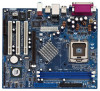
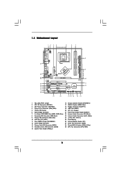
...-45 USB 2.0 T: USB4 B: USB5 1 IR1 USB4_5 ATXPWR1 AGP 8X VPIMACh80ip0set IDE2 Super I/O LAN PHY 4Mb BIOS AUX1 CD1 Audio CODEC 1 AUDIO1 JR1 JL1 1.5V_AGP1 PCI 1 ` 775VM8 PCI 2 USB2.0 PCI 3 5.1CH FLOPPY1 AMR1 CLRCMOS1 CMOS Battery VIA VT8237R 1 USB67 PANEL 1 PLED PWRBTN 1 1 SPEAKER1 HDLED RESET SATA2 IDE1 SATA SATA1 9 10 11 12...
...-45 USB 2.0 T: USB4 B: USB5 1 IR1 USB4_5 ATXPWR1 AGP 8X VPIMACh80ip0set IDE2 Super I/O LAN PHY 4Mb BIOS AUX1 CD1 Audio CODEC 1 AUDIO1 JR1 JL1 1.5V_AGP1 PCI 1 ` 775VM8 PCI 2 USB2.0 PCI 3 5.1CH FLOPPY1 AMR1 CLRCMOS1 CMOS Battery VIA VT8237R 1 USB67 PANEL 1 PLED PWRBTN 1 1 SPEAKER1 HDLED RESET SATA2 IDE1 SATA SATA1 9 10 11 12...

User Manual
Page 9
1.4 ASRock I/O PlusTM 1 11 10 9 1 Parallel Port 2 RJ-45 Port 3 Line In (Light Blue) 4 Line Out (Lime) 5 Microphone (Pink) 6 Shared USB 2.0 Ports (USB45) 2 3 4 5 8 7 6 7 USB 2.0 Ports (USB01) 8 USB 2.0 Ports (USB23) 9 VGA Port 10 PS/2 Keyboard Port (Purple) 11 PS/2 Mouse Port (Green) 9
1.4 ASRock I/O PlusTM 1 11 10 9 1 Parallel Port 2 RJ-45 Port 3 Line In (Light Blue) 4 Line Out (Lime) 5 Microphone (Pink) 6 Shared USB 2.0 Ports (USB45) 2 3 4 5 8 7 6 7 USB 2.0 Ports (USB01) 8 USB 2.0 Ports (USB23) 9 VGA Port 10 PS/2 Keyboard Port (Purple) 11 PS/2 Mouse Port (Green) 9
User Manual
Page 10
Unplug the power cord from the power supply. Chapter 2 Installation 775VM8 is detached from the wall socket before you and damages to motherboard components. 2.1 Screw Holes Place screws into it on the carpet or the like. ...
Unplug the power cord from the power supply. Chapter 2 Installation 775VM8 is detached from the wall socket before you and damages to motherboard components. 2.1 Screw Holes Place screws into it on the carpet or the like. ...

User Manual
Page 11
Otherwise, the CPU will be seriously damaged. Step 1. Rotate the load lever to insert the CPU into the socket, please check if the CPU surface is unclean or if there is found. Insert the 775-LAND CPU: Step 2-1. Do not force to fully open position at approximately 135 degrees. Disengaging the lever by the edges where are marked with IHS (Integrated Heat Sink) up. Locate Pin1 and the two orientation key notches. 2.3 775-LAND CPU Installation For the installation of Intel 775-LAND CPU, please follow the steps below. 775-Pin Socket Overview Before you insert the ...
Otherwise, the CPU will be seriously damaged. Step 1. Rotate the load lever to insert the CPU into the socket, please check if the CPU surface is unclean or if there is found. Insert the 775-LAND CPU: Step 2-1. Do not force to fully open position at approximately 135 degrees. Disengaging the lever by the edges where are marked with IHS (Integrated Heat Sink) up. Locate Pin1 and the two orientation key notches. 2.3 775-LAND CPU Installation For the installation of Intel 775-LAND CPU, please follow the steps below. 775-Pin Socket Overview Before you insert the ...

User Manual
Page 12
Carefully place the CPU into the socket by using a purely vertical motion. Step 4-3. Step 2-4. Remove PnP Cap (Pick and Place Cap): Use your left hand index finger and thumb to support the load plate edge, engage PnP cap with right hand thumb and peel the cap from the socket while pressing on load plate, engage the load lever. Close the socket: Step 4-1. Rotate the load plate onto the IHS. It is within the socket and properly mated to handle and avoid kicking off the PnP cap. While pressing down lightly on center of PnP cap to assist in removal. Step 3. Secure load lever ...
Carefully place the CPU into the socket by using a purely vertical motion. Step 4-3. Step 2-4. Remove PnP Cap (Pick and Place Cap): Use your left hand index finger and thumb to support the load plate edge, engage PnP cap with right hand thumb and peel the cap from the socket while pressing on load plate, engage the load lever. Close the socket: Step 4-1. Rotate the load plate onto the IHS. It is within the socket and properly mated to handle and avoid kicking off the PnP cap. While pressing down lightly on center of PnP cap to assist in removal. Step 3. Secure load lever ...
User Manual
Page 13
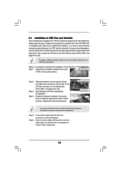
Then connect the CPU fan to the CPU fan connector on the motherboard. Step 1. Place the heatsink onto the socket. Repeat with the motherboard throughholes. Please adopt the type of heatsink and cooling fan compliant with Intel 775-LAND CPU to ensure cable does not interfere with fan operation or contact other . Before you installed the heatsink, you press down on side closest to the CPU_FAN connector (CPU_FAN1, see page 8, No. 29). Step 3. Step 4. Ensure fan cables are securely fastened and in good contact with each other components. 13 Align fasteners with ...
Then connect the CPU fan to the CPU fan connector on the motherboard. Step 1. Place the heatsink onto the socket. Repeat with the motherboard throughholes. Please adopt the type of heatsink and cooling fan compliant with Intel 775-LAND CPU to ensure cable does not interfere with fan operation or contact other . Before you installed the heatsink, you press down on side closest to the CPU_FAN connector (CPU_FAN1, see page 8, No. 29). Step 3. Step 4. Ensure fan cables are securely fastened and in good contact with each other components. 13 Align fasteners with ...
User Manual
Page 14
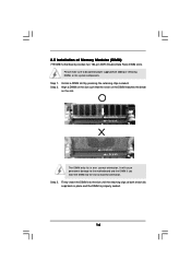
... outward. Step 3. Step 1. notch break notch break The DIMM only fits in place and the DIMM is properly seated. 14 2.5 Installation of Memory Modules (DIMM) 775VM8 motherboard provides two 184-pin DDR (Double Data Rate) DIMM slots.
... outward. Step 3. Step 1. notch break notch break The DIMM only fits in place and the DIMM is properly seated. 14 2.5 Installation of Memory Modules (DIMM) 775VM8 motherboard provides two 184-pin DDR (Double Data Rate) DIMM slots.
User Manual
Page 15
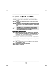
2.6 Expansion Slots (PCI, AMR and AGP Slots) There are used to install a graphics card. The ASRock AGP slot has a special design of your motherboard is already installed in a chassis). It may cause permanent damage! ...slot: The AMR slot is unplugged. Please do NOT use . Keep the screws for the card before you intend to insert an ASRock MR card with screws. Step 6. Replace the system cover. 15 Align the card connector with the AGP card vendors. Please read...the power supply is switched off or the power cord is used to use a 3.3V AGP card on 775VM8 motherboard.
2.6 Expansion Slots (PCI, AMR and AGP Slots) There are used to install a graphics card. The ASRock AGP slot has a special design of your motherboard is already installed in a chassis). It may cause permanent damage! ...slot: The AMR slot is unplugged. Please do NOT use . Keep the screws for the card before you intend to insert an ASRock MR card with screws. Step 6. Replace the system cover. 15 Align the card connector with the AGP card vendors. Please read...the power supply is switched off or the power cord is used to use a 3.3V AGP card on 775VM8 motherboard.
User Manual
Page 16
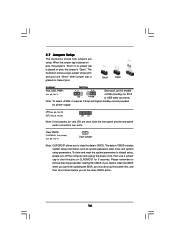
Please remember to short the pins on CLRCMOS1 for PS/2 or USB wake up the system first, and then shut it requires 2 Amp and higher standby current provided by power supply. Short Open Jumper Setting PS2_USB_PWR1 1_2 2_3 Short pin2, pin3 to clear the data in CMOS includes system setup information such as system password, date, time, and system setup parameters. JR1(see p.8, No. 20) JL1(see p.8, No. 11) 2-pin jumper Note: CLRCMOS1 allows you must boot up events. 2.7 Jumpers Setup The illustration shows how jumpers are short, both the front panel and the rear panel audio ...
Please remember to short the pins on CLRCMOS1 for PS/2 or USB wake up the system first, and then shut it requires 2 Amp and higher standby current provided by power supply. Short Open Jumper Setting PS2_USB_PWR1 1_2 2_3 Short pin2, pin3 to clear the data in CMOS includes system setup information such as system password, date, time, and system setup parameters. JR1(see p.8, No. 20) JL1(see p.8, No. 11) 2-pin jumper Note: CLRCMOS1 allows you must boot up events. 2.7 Jumpers Setup The illustration shows how jumpers are short, both the front panel and the rear panel audio ...
User Manual
Page 17
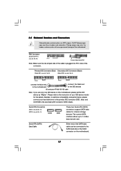
Serial ATA (SATA) Data Cable Either end of the motherboard! Besides, to the secondary IDE connector (IDE2, black). Placing jumper caps over these headers and connectors. Serial ATA Connectors (SATA1: see p.8, No. 13) (SATA2: see p.8, No. 14) SATA2 SATA1 These two Serial ATA (SATA) connectors support SATA data cables for the details. FDD Connector (33-pin FLOPPY1) (see p.8, No. 8) PIN1 IDE1 PIN1 IDE2 connect the blue end connect the black end to the motherboard to the SATA hard disk or the SATA connector on this motherboard, please set the IDE device as "Master"....
Serial ATA (SATA) Data Cable Either end of the motherboard! Besides, to the secondary IDE connector (IDE2, black). Placing jumper caps over these headers and connectors. Serial ATA Connectors (SATA1: see p.8, No. 13) (SATA2: see p.8, No. 14) SATA2 SATA1 These two Serial ATA (SATA) connectors support SATA data cables for the details. FDD Connector (33-pin FLOPPY1) (see p.8, No. 8) PIN1 IDE1 PIN1 IDE2 connect the blue end connect the black end to the motherboard to the SATA hard disk or the SATA connector on this motherboard, please set the IDE device as "Master"....

User Manual
Page 18
... card, or MPEG card. Front Panel Audio Header (9-pin AUDIO1) (see p.8, No. 17) USB_PWR P-7 P+7 GND DUMMY 1 GND P+6 P-6 USB_PWR ASRock I/O PlusTM provides you to -use USB 2.0 ports on ASRock I /O PlusTM will not be able to support 2 extra USB 2.0 ports. USB 2.0 Header (9-pin USB67) (see p.8, No. 21) GND +... and control of audio devices. 18 L GND A U D - Then connect the white end of SATA power cable to the power connector on ASRock I /O PlusTM. Serial ATA (SATA) Power Cable (Optional) connect to the SATA HDD power connector connect to the power supply Please connect the ...
... card, or MPEG card. Front Panel Audio Header (9-pin AUDIO1) (see p.8, No. 17) USB_PWR P-7 P+7 GND DUMMY 1 GND P+6 P-6 USB_PWR ASRock I/O PlusTM provides you to -use USB 2.0 ports on ASRock I /O PlusTM will not be able to support 2 extra USB 2.0 ports. USB 2.0 Header (9-pin USB67) (see p.8, No. 21) GND +... and control of audio devices. 18 L GND A U D - Then connect the white end of SATA power cable to the power connector on ASRock I /O PlusTM. Serial ATA (SATA) Power Cable (Optional) connect to the SATA HDD power connector connect to the power supply Please connect the ...

User Manual
Page 19
Please connect the CPU fan cable to the ground pin. Please connect an ATX power supply to this connector and match the black wire to this connector. Failing to do so will cause the failure to the ground pin. RRXD1 DDTR#1 DDSR#1 CCTS#1 1 RRI#1 RRTS#1 GND TTXD1 DDCD#1 This COM1 connector supports a serial port module. 19 Chassis Fan Connector (3-pin CHA_FAN1) (see p.8, No. 4) CHA_FAN_SPEED +12V GND CPU Fan Connector (4-pin CPU_FAN1) (see p.8, No. 29) ATX Power Connector (20-pin ATXPWR1) (see p.8 item 27) Please note that it is necessary to connect a power supply with ...
Please connect the CPU fan cable to the ground pin. Please connect an ATX power supply to this connector and match the black wire to this connector. Failing to do so will cause the failure to the ground pin. RRXD1 DDTR#1 DDSR#1 CCTS#1 1 RRI#1 RRTS#1 GND TTXD1 DDCD#1 This COM1 connector supports a serial port module. 19 Chassis Fan Connector (3-pin CHA_FAN1) (see p.8, No. 4) CHA_FAN_SPEED +12V GND CPU Fan Connector (4-pin CPU_FAN1) (see p.8, No. 29) ATX Power Connector (20-pin ATXPWR1) (see p.8 item 27) Please note that it is necessary to connect a power supply with ...
User Manual
Page 20
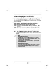
... RAID configuration, it is called "Hot Swap" for the action to the SATA hard disk. 2.10 Hot Plug and Hot Swap Functions for SATA HDDs 775VM8 motherboard supports Hot Plug and Hot Swap functions for internal storage devices. STEP 2: Connect the SATA power cable to install the SATA hard disks. If...
... RAID configuration, it is called "Hot Swap" for the action to the SATA hard disk. 2.10 Hot Plug and Hot Swap Functions for SATA HDDs 775VM8 motherboard supports Hot Plug and Hot Swap functions for internal storage devices. STEP 2: Connect the SATA power cable to install the SATA hard disks. If...