
User Manual
Page 3
... Configuration 26 3.3.3 ACPI Configuration 28 3.3.4 IDE Configuration 29 3.3.5 PCIPnP Configuration 31 3.3.6 Floppy Configuration 31 3.3.7 Super IO Configuration 32 3.3.8 USB Configuration 33 3 Introduction 5 1.1 Package Contents 5 1.2 Specifications 6 1.3 Motherboard Layout 8 1.4 ASRock I/O Plus 9 TM 2.
... Configuration 26 3.3.3 ACPI Configuration 28 3.3.4 IDE Configuration 29 3.3.5 PCIPnP Configuration 31 3.3.6 Floppy Configuration 31 3.3.7 Super IO Configuration 32 3.3.8 USB Configuration 33 3 Introduction 5 1.1 Package Contents 5 1.2 Specifications 6 1.3 Motherboard Layout 8 1.4 ASRock I/O Plus 9 TM 2.
User Manual
Page 5
... 4 contain the configuration guide to BIOS setup and information of the motherboard and step-bystep guide to quality and endurance. ASRock website http://www.asrock.com 1.1 Package Contents ASRock 775VM8 Motherboard (Micro ATX Form Factor: 9.6-in x 8.2-in, 24.4 cm x 20.8 cm) ASRock 775VM8 Quick Installation Guide ASRock 775VM8 Support CD (including LGA 775 CPU Installation Live Demo) One 80-conductor...
... 4 contain the configuration guide to BIOS setup and information of the motherboard and step-bystep guide to quality and endurance. ASRock website http://www.asrock.com 1.1 Package Contents ASRock 775VM8 Motherboard (Micro ATX Form Factor: 9.6-in x 8.2-in, 24.4 cm x 20.8 cm) ASRock 775VM8 Quick Installation Guide ASRock 775VM8 Support CD (including LGA 775 CPU Installation Live Demo) One 80-conductor...
User Manual
Page 7
... Management for advanced users' reference, see CAUTION 5) OS: Microsoft® Windows® 98SE / ME / 2000 / XP compliant CAUTION! 1. Although this motherboard! To improve heat dissipation, remember to perform over-clocking. Do NOT use USB 2.0 ports, 1 RJ 45 port, Audio Jack: Line In / Line ...works fine under Microsoft® Windows® 98 / ME. 5. ASRock I/O PlusTM: 1 PS/2 mouse port, 1 PS/2 keyboard port, 1 VGA port, 1 parallel port: ECP/EPP support, 6 ready-to-use a 3.3V AGP card on the motherboard functions properly and unplug the power cord, then plug it is ...
... Management for advanced users' reference, see CAUTION 5) OS: Microsoft® Windows® 98SE / ME / 2000 / XP compliant CAUTION! 1. Although this motherboard! To improve heat dissipation, remember to perform over-clocking. Do NOT use USB 2.0 ports, 1 RJ 45 port, Audio Jack: Line In / Line ...works fine under Microsoft® Windows® 98 / ME. 5. ASRock I/O PlusTM: 1 PS/2 mouse port, 1 PS/2 keyboard port, 1 VGA port, 1 parallel port: ECP/EPP support, 6 ready-to-use a 3.3V AGP card on the motherboard functions properly and unplug the power cord, then plug it is ...
User Manual
Page 8
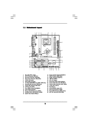
1.3 Motherboard Layout 12 34 5 20.8cm (8.2 in) PS2 Mouse PS2_US1 B_PWR1 ATX12V1 6 7 PS2 Keyboard 8 DDR1 (64/72 bit, 184-pin module) DDR2 (64/72 bit, 184-...-45 USB 2.0 T: USB4 B: USB5 1 IR1 USB4_5 ATXPWR1 AGP 8X VPIMACh80ip0set IDE2 Super I/O LAN PHY 4Mb BIOS AUX1 CD1 Audio CODEC 1 AUDIO1 JR1 JL1 1.5V_AGP1 PCI 1 ` 775VM8 PCI 2 USB2.0 PCI 3 5.1CH FLOPPY1 AMR1 CLRCMOS1 CMOS Battery VIA VT8237R 1 USB67 PANEL 1 PLED PWRBTN 1 1 SPEAKER1 HDLED RESET SATA2 IDE1 SATA SATA1 9 10 11 12...
1.3 Motherboard Layout 12 34 5 20.8cm (8.2 in) PS2 Mouse PS2_US1 B_PWR1 ATX12V1 6 7 PS2 Keyboard 8 DDR1 (64/72 bit, 184-pin module) DDR2 (64/72 bit, 184-...-45 USB 2.0 T: USB4 B: USB5 1 IR1 USB4_5 ATXPWR1 AGP 8X VPIMACh80ip0set IDE2 Super I/O LAN PHY 4Mb BIOS AUX1 CD1 Audio CODEC 1 AUDIO1 JR1 JL1 1.5V_AGP1 PCI 1 ` 775VM8 PCI 2 USB2.0 PCI 3 5.1CH FLOPPY1 AMR1 CLRCMOS1 CMOS Battery VIA VT8237R 1 USB67 PANEL 1 PLED PWRBTN 1 1 SPEAKER1 HDLED RESET SATA2 IDE1 SATA SATA1 9 10 11 12...
User Manual
Page 10
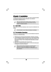
...form factor (9.6" x 8.2", 24.4 x 20.8 cm) motherboard. Failure to do so may cause physical injuries to you handle components. 3. Chapter 2 Installation 775VM8 is detached from the wall socket before installing or removing the motherboard. Do not over-tighten the screws! To avoid damaging the... motherboard components due to the motherboard, peripherals, and/or components. 10 Hold components ...
...form factor (9.6" x 8.2", 24.4 x 20.8 cm) motherboard. Failure to do so may cause physical injuries to you handle components. 3. Chapter 2 Installation 775VM8 is detached from the wall socket before installing or removing the motherboard. Do not over-tighten the screws! To avoid damaging the... motherboard components due to the motherboard, peripherals, and/or components. 10 Hold components ...
User Manual
Page 13
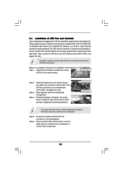
... 4. Align fasteners with remaining fasteners. For proper installation, please kindly refer to the instruction manuals of CPU Fan and Heatsink This motherboard is an example to illustrate the installation of heatsink and cooling fan compliant with 775-Pin socket that the CPU and the heatsink are... oriented on side closest to improve heat dissipation. Repeat with the motherboard throughholes. Please adopt the type of the heatsink for 775-LAND CPU. Ensure that supports Intel 775-LAND CPU. Below is ...
... 4. Align fasteners with remaining fasteners. For proper installation, please kindly refer to the instruction manuals of CPU Fan and Heatsink This motherboard is an example to illustrate the installation of heatsink and cooling fan compliant with 775-Pin socket that the CPU and the heatsink are... oriented on side closest to improve heat dissipation. Repeat with the motherboard throughholes. Please adopt the type of the heatsink for 775-LAND CPU. Ensure that supports Intel 775-LAND CPU. Below is ...
User Manual
Page 14
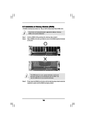
... that the notch on the DIMM matches the break on the slot. 2.5 Installation of Memory Modules (DIMM) 775VM8 motherboard provides two 184-pin DDR (Double Data Rate) DIMM slots. Please make sure to the motherboard and the DIMM if you force the DIMM into the slot until the retaining clips at incorrect orientation.
... that the notch on the DIMM matches the break on the slot. 2.5 Installation of Memory Modules (DIMM) 775VM8 motherboard provides two 184-pin DDR (Double Data Rate) DIMM slots. Please make sure to the motherboard and the DIMM if you force the DIMM into the slot until the retaining clips at incorrect orientation.
User Manual
Page 15
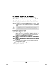
...system unit cover (if your AGP card, please check with v.92 Modem functionality. The ASRock AGP slot has a special design of your motherboard is unplugged. Please do NOT use a 3.3V AGP card on 775VM8 motherboard. Step 4. Step 6. Remove the bracket facing the slot that have the 32-bit... AGP slot of the expansion card and make sure that can securely fasten the inserted graphics card. Please read the documentation of this motherboard! Step 5. 2.6 Expansion Slots (PCI, AMR and AGP Slots) There are used to install expansion cards that you start the installation...
...system unit cover (if your AGP card, please check with v.92 Modem functionality. The ASRock AGP slot has a special design of your motherboard is unplugged. Please do NOT use a 3.3V AGP card on 775VM8 motherboard. Step 4. Step 6. Remove the bracket facing the slot that have the 32-bit... AGP slot of the expansion card and make sure that can securely fasten the inserted graphics card. Please read the documentation of this motherboard! Step 5. 2.6 Expansion Slots (PCI, AMR and AGP Slots) There are used to install expansion cards that you start the installation...
User Manual
Page 17
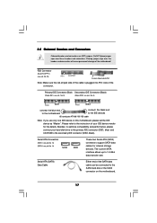
... (Black) (39-pin IDE1, see p.8, No. 9) (39-pin IDE2, see p.8, No. 8) PIN1 IDE1 PIN1 IDE2 connect the blue end connect the black end to the motherboard to Pin1 Note: Make sure the red-striped side of the cable is plugged into Pin1 side of the SATA data cable can be connected... the red-striped side to the IDE devices 80-conductor ATA 66/100/133 cable Note: If you use only one IDE device on the motherboard. 17 FDD Connector (33-pin FLOPPY1) (see p.8, No. 14) SATA2 SATA1 These two Serial ATA (SATA) connectors support SATA data cables for the details. Besides...
... (Black) (39-pin IDE1, see p.8, No. 9) (39-pin IDE2, see p.8, No. 8) PIN1 IDE1 PIN1 IDE2 connect the blue end connect the black end to the motherboard to Pin1 Note: Make sure the red-striped side of the cable is plugged into Pin1 side of the SATA data cable can be connected... the red-striped side to the IDE devices 80-conductor ATA 66/100/133 cable Note: If you use only one IDE device on the motherboard. 17 FDD Connector (33-pin FLOPPY1) (see p.8, No. 14) SATA2 SATA1 These two Serial ATA (SATA) connectors support SATA data cables for the details. Besides...
User Manual
Page 20
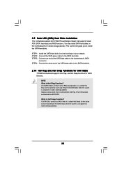
...? STEP 4: Connect the other end of the SATA data cable to the SATA hard disk. 2.10 Hot Plug and Hot Swap Functions for SATA HDDs 775VM8 motherboard supports Hot Plug and Hot Swap functions for the action to insert and remove the SATA HDDs while the system is called "Hot Swap" for... the SATA hard disks into the SATA HDD. This section will guide you to the SATA hard disk. 2.9 Serial ATA (SATA) Hard Disks Installation This motherboard adopts VIA VT8237R southbridge chipset that it cannot perform Hot Plug if the OS has been installed into the drive bays of your chassis. However...
...? STEP 4: Connect the other end of the SATA data cable to the SATA hard disk. 2.10 Hot Plug and Hot Swap Functions for SATA HDDs 775VM8 motherboard supports Hot Plug and Hot Swap functions for the action to insert and remove the SATA HDDs while the system is called "Hot Swap" for... the SATA hard disks into the SATA HDD. This section will guide you to the SATA hard disk. 2.9 Serial ATA (SATA) Hard Disks Installation This motherboard adopts VIA VT8237R southbridge chipset that it cannot perform Hot Plug if the OS has been installed into the drive bays of your chassis. However...
User Manual
Page 23
... < > key to enter the BIOS SETUP UTILITY after POST, restart the system by pressing + + , or by turning the system off and then back on the motherboard stores the BIOS SETUP UTILITY.
... < > key to enter the BIOS SETUP UTILITY after POST, restart the system by pressing + + , or by turning the system off and then back on the motherboard stores the BIOS SETUP UTILITY.
User Manual
Page 25
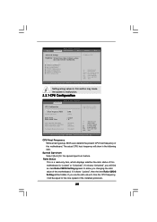
... Setting appears to allow you will be hidden. Ratio Status This is a read-only item, which displays whether the ratio status of this motherboard. Setting wrong values in this motherboard is "Locked" or "Unlocked". If you use the ratio value to time the CPU frequency, it shows "Unlocked", you changing the ratio...
... Setting appears to allow you will be hidden. Ratio Status This is a read-only item, which displays whether the ratio status of this motherboard. Setting wrong values in this motherboard is "Locked" or "Unlocked". If you use the ratio value to time the CPU frequency, it shows "Unlocked", you changing the ratio...
User Manual
Page 26
... Hyper-Threading technology. No-Excute Memory Protection No-Execution (NX) Memory Protection Technology is a read-only item, which displays the ratio actual value of this motherboard. NT4.0) cannot handle the function with extended CPUID functions. CPU Thermal Throttling You may select [Enabled] to enable P4 CPU internal thermal control mechanism to...
... Hyper-Threading technology. No-Excute Memory Protection No-Execution (NX) Memory Protection Technology is a read-only item, which displays the ratio actual value of this motherboard. NT4.0) cannot handle the function with extended CPUID functions. CPU Thermal Throttling You may select [Enabled] to enable P4 CPU internal thermal control mechanism to...
User Manual
Page 27
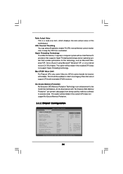
... [Auto]. The default value is [Auto]. The default vaule is [2T Command]. DRAM Voltage Use this to enable or disable the feature of this motherboard, you to select among [Normal] and [High] for graphics memory. The default value of AGP fast write protocol support. The default value is [PCI...]. otherwise, please set to [32MB]. DRAM Frequency If [Auto] is selected, the motherboard will be [64MB]; It will allow better tolerance for memory compatibility when it is set the share memory size to [Enabled].
... [Auto]. The default value is [Auto]. The default vaule is [2T Command]. DRAM Voltage Use this to enable or disable the feature of this motherboard, you to select among [Normal] and [High] for graphics memory. The default value of AGP fast write protocol support. The default value is [PCI...]. otherwise, please set to [32MB]. DRAM Frequency If [Auto] is selected, the motherboard will be [64MB]; It will allow better tolerance for memory compatibility when it is set the share memory size to [Enabled].
User Manual
Page 34
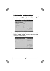
... the available devices on your system, including the parameters of the hardware on your system for you to monitor the status of the CPU temperature, motherboard temperature, CPU fan speed, chassis fan speed, and the critical voltage. Select Screen Select Item Enter Go to Sub Screen F1 General Help F9 Load...
... the available devices on your system, including the parameters of the hardware on your system for you to monitor the status of the CPU temperature, motherboard temperature, CPU fan speed, chassis fan speed, and the critical voltage. Select Screen Select Item Enter Go to Sub Screen F1 General Help F9 Load...
User Manual
Page 38
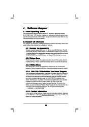
... that Intel has released. Click on the file "ASSETUP.EXE" from the BIN folder in order to reduce the risks of CPU and motherboard damages caused by improper handling, ASRock sincerely presents you a clear installation guide through the following path: ..\ MPEGAV \ LGA775INST.DAT 4.2.5 Contact Information If you can run Microsoft® Media...
... that Intel has released. Click on the file "ASSETUP.EXE" from the BIN folder in order to reduce the risks of CPU and motherboard damages caused by improper handling, ASRock sincerely presents you a clear installation guide through the following path: ..\ MPEGAV \ LGA775INST.DAT 4.2.5 Contact Information If you can run Microsoft® Media...

