
User Manual
Page 3
... Slots (PCI, AMR, and AGP Slots 15 2.7 Jumpers Setup 16 2.8 Onboard Headers and Connectors 17 2.9 Serial ATA (SATA) Hard Disks Installation 20 2.10 Hot Plug and Hot Swap Functions for SATA HDDs .... 20 2.11 Installing Windows 2000 / Windows XP / Windows XP 64-bit With RAID Functions 21 2.11.1 Installing... 3.3.4 IDE Configuration 29 3.3.5 PCIPnP Configuration 31 3.3.6 Floppy Configuration 31 3.3.7 Super IO Configuration 32 3.3.8 USB Configuration 33 3 Introduction 5 1.1 Package Contents 5 1.2 Specifications 6 1.3 Motherboard Layout 8 1.4 ASRock I/O Plus 9 TM 2. Contents 1.
... Slots (PCI, AMR, and AGP Slots 15 2.7 Jumpers Setup 16 2.8 Onboard Headers and Connectors 17 2.9 Serial ATA (SATA) Hard Disks Installation 20 2.10 Hot Plug and Hot Swap Functions for SATA HDDs .... 20 2.11 Installing Windows 2000 / Windows XP / Windows XP 64-bit With RAID Functions 21 2.11.1 Installing... 3.3.4 IDE Configuration 29 3.3.5 PCIPnP Configuration 31 3.3.6 Floppy Configuration 31 3.3.7 Super IO Configuration 32 3.3.8 USB Configuration 33 3 Introduction 5 1.1 Package Contents 5 1.2 Specifications 6 1.3 Motherboard Layout 8 1.4 ASRock I/O Plus 9 TM 2. Contents 1.
User Manual
Page 5
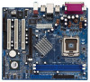
... to the hardware installation. In case any modifications of the Support CD. ASRock website http://www.asrock.com 1.1 Package Contents ASRock 775VM8 Motherboard (Micro ATX Form Factor: 9.6-in x 8.2-in Floppy Drive One Serial ATA (SATA) Cable One Serial ATA (SATA) HDD Power Cable(Optional) One ASRock I/O PlusTM Shield One COM Port Bracket 5 Introduction Thank you for a 3.5-in...
... to the hardware installation. In case any modifications of the Support CD. ASRock website http://www.asrock.com 1.1 Package Contents ASRock 775VM8 Motherboard (Micro ATX Form Factor: 9.6-in x 8.2-in Floppy Drive One Serial ATA (SATA) Cable One Serial ATA (SATA) HDD Power Cable(Optional) One ASRock I/O PlusTM Shield One COM Port Bracket 5 Introduction Thank you for a 3.5-in...

User Manual
Page 6
... PM800, FSB @ 800/533 MHz, with Intel® Hyper-Threading Technology ready (see CAUTION 1) South Bridge: VIA VT8237R, supports USB 2.0, ATA 133, SATA 1.5Gb/s Memory: 2 DDR DIMM Slots: DDR1 and DDR2 1 DDR DIMM Slot Supports PC3200 (DDR400), Max. 1GB, 2 DDR DIMM Slots Supports PC2700 (....3u (10/100 Ethernet), supports Wake-On-LAN Hardware Monitor: CPU temperature sensing Chassis temperature sensing CPU overheat shutdown to protect CPU life (ASRock U-COP)(see CAUTION 2) CPU fan tachometer Chassis fan tachometer Voltage monitoring: +12V, +5V, +3.3V, Vcore PCI slots: 3 slots with...
... PM800, FSB @ 800/533 MHz, with Intel® Hyper-Threading Technology ready (see CAUTION 1) South Bridge: VIA VT8237R, supports USB 2.0, ATA 133, SATA 1.5Gb/s Memory: 2 DDR DIMM Slots: DDR1 and DDR2 1 DDR DIMM Slot Supports PC3200 (DDR400), Max. 1GB, 2 DDR DIMM Slots Supports PC2700 (....3u (10/100 Ethernet), supports Wake-On-LAN Hardware Monitor: CPU temperature sensing Chassis temperature sensing CPU overheat shutdown to protect CPU life (ASRock U-COP)(see CAUTION 2) CPU fan tachometer Chassis fan tachometer Voltage monitoring: +12V, +5V, +3.3V, Vcore PCI slots: 3 slots with...
User Manual
Page 8
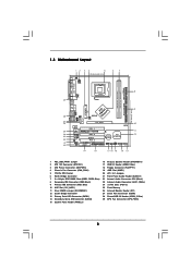
... IDE2 Super I/O LAN PHY 4Mb BIOS AUX1 CD1 Audio CODEC 1 AUDIO1 JR1 JL1 1.5V_AGP1 PCI 1 ` 775VM8 PCI 2 USB2.0 PCI 3 5.1CH FLOPPY1 AMR1 CLRCMOS1 CMOS Battery VIA VT8237R 1 USB67 PANEL 1 PLED PWRBTN 1 1 SPEAKER1 HDLED RESET SATA2 IDE1 SATA SATA1 9 10 11 12 19 18 17 16 15 14 13 1 PS2_USB_PWR1 Jumper 2 ATX 12V...
... IDE2 Super I/O LAN PHY 4Mb BIOS AUX1 CD1 Audio CODEC 1 AUDIO1 JR1 JL1 1.5V_AGP1 PCI 1 ` 775VM8 PCI 2 USB2.0 PCI 3 5.1CH FLOPPY1 AMR1 CLRCMOS1 CMOS Battery VIA VT8237R 1 USB67 PANEL 1 PLED PWRBTN 1 1 SPEAKER1 HDLED RESET SATA2 IDE1 SATA SATA1 9 10 11 12 19 18 17 16 15 14 13 1 PS2_USB_PWR1 Jumper 2 ATX 12V...
User Manual
Page 17
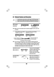
... connectors will cause permanent damage of the connector. FDD Connector (33-pin FLOPPY1) (see p.8, No. 14) SATA2 SATA1 These two Serial ATA (SATA) connectors support SATA data cables for the details. Serial ATA Connectors (SATA1: see p.8, No. 13) (SATA2: see p.8, No. 18) Pin1 FLOPPY1 the red... 2.8 Onboard Headers and Connectors Onboard headers and connectors are NOT jumpers. Besides, to the secondary IDE connector (IDE2, black). Serial ATA (SATA) Data Cable Either end of your hard disk drive to the primary IDE connector (IDE1, blue) and CD-ROM to optimize compatibility and ...
... connectors will cause permanent damage of the connector. FDD Connector (33-pin FLOPPY1) (see p.8, No. 14) SATA2 SATA1 These two Serial ATA (SATA) connectors support SATA data cables for the details. Serial ATA Connectors (SATA1: see p.8, No. 13) (SATA2: see p.8, No. 18) Pin1 FLOPPY1 the red... 2.8 Onboard Headers and Connectors Onboard headers and connectors are NOT jumpers. Besides, to the secondary IDE connector (IDE2, black). Serial ATA (SATA) Data Cable Either end of your hard disk drive to the primary IDE connector (IDE1, blue) and CD-ROM to optimize compatibility and ...

User Manual
Page 18
... P-7 P+7 GND DUMMY 1 GND P+6 P-6 USB_PWR ASRock I/O PlusTM provides you to receive stereo audio input from sound sources such as a CD-ROM, DVD-ROM, TV tuner card, or MPEG card. O U T- Then connect the white end of SATA power cable to the power connector of SATA power cable to the power connector on...GND GND CD-L AUX1 CD1 These connectors allow you 6 ready-to-use USB 2.0 ports on the drive. Serial ATA (SATA) Power Cable (Optional) connect to the SATA HDD power connector connect to the power supply Please connect the black end of the power supply. When using the front ...
... P-7 P+7 GND DUMMY 1 GND P+6 P-6 USB_PWR ASRock I/O PlusTM provides you to receive stereo audio input from sound sources such as a CD-ROM, DVD-ROM, TV tuner card, or MPEG card. O U T- Then connect the white end of SATA power cable to the power connector of SATA power cable to the power connector on...GND GND CD-L AUX1 CD1 These connectors allow you 6 ready-to-use USB 2.0 ports on the drive. Serial ATA (SATA) Power Cable (Optional) connect to the SATA HDD power connector connect to the power supply Please connect the black end of the power supply. When using the front ...
User Manual
Page 20
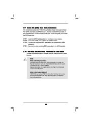
... the SATA hard disks into the SATA HDD. STEP 2: Connect the SATA power cable to install the SATA hard disks. If SATA HDDs are NOT set for RAID configuration, it is called "Hot Swap" for the action to the SATA hard disk. 2.10 Hot Plug and Hot Swap Functions for SATA HDDs 775VM8 motherboard ...supports Hot Plug and Hot Swap functions for internal storage devices. However, please note that supports Serial ATA (SATA) hard disks and RAID functions. If the SATA HDDs are built as RAID1 then it is called "Hot...
... the SATA hard disks into the SATA HDD. STEP 2: Connect the SATA power cable to install the SATA hard disks. If SATA HDDs are NOT set for RAID configuration, it is called "Hot Swap" for the action to the SATA hard disk. 2.10 Hot Plug and Hot Swap Functions for SATA HDDs 775VM8 motherboard ...supports Hot Plug and Hot Swap functions for internal storage devices. However, please note that supports Serial ATA (SATA) hard disks and RAID functions. If the SATA HDDs are built as RAID1 then it is called "Hot...
User Manual
Page 21
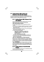
...selection appears. The system will see the message on your SATA HDDs with RAID functions, please follow the below steps. After making a SATA driver diskette and using "SATA RAID BIOS" to set RAID configuration. Insert the ASRock Support CD into the floppy diskette. E. Please refer ...to the document in the Support CD, "Guide to SATA Hard Disks Installation and RAID Configuration", ...
...selection appears. The system will see the message on your SATA HDDs with RAID functions, please follow the below steps. After making a SATA driver diskette and using "SATA RAID BIOS" to set RAID configuration. Insert the ASRock Support CD into the floppy diskette. E. Please refer ...to the document in the Support CD, "Guide to SATA Hard Disks Installation and RAID Configuration", ...
User Manual
Page 22
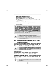
... at the following path: .. \ VIA RAID Tool 1. A. Enter BIOS SETUP UTILITY ¡÷Advanced screen ¡÷IDE Configuration. After setting up BIOS. After making a SATA driver diskette, you can start to install Windows XP 64bit on your IDE HDDs instead of Windows 2000 / Windows XP / Windows XP 64-bit OS... / XP 64-bit on your system. If you don't have to set up RAID functions, there is located in the folder at the following path: .. \ SATA RAID BIOS and the document in the support CD, "Guide to VIA RAID Tool", which is no need to [non-RAID].
... at the following path: .. \ VIA RAID Tool 1. A. Enter BIOS SETUP UTILITY ¡÷Advanced screen ¡÷IDE Configuration. After setting up BIOS. After making a SATA driver diskette, you can start to install Windows XP 64bit on your IDE HDDs instead of Windows 2000 / Windows XP / Windows XP 64-bit OS... / XP 64-bit on your system. If you don't have to set up RAID functions, there is located in the folder at the following path: .. \ SATA RAID BIOS and the document in the support CD, "Guide to VIA RAID Tool", which is no need to [non-RAID].
User Manual
Page 29
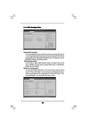
... v02.54 (C) Copyright 1985-2003, American Megatrends, Inc. 29 The default value of this item to operate RAID function on SATA HDDs, please select [non-RAID]. OnBoard IDE Controller You may set the IDE configuration for the device that you don't want to adjust... SATA Operation Mode. SATA Operation Mode Use this option is [RAID]. Configuration options: [Disabled], [Primary], [Secondary], [Both]. IDE Device Configuration You may enable either ...
... v02.54 (C) Copyright 1985-2003, American Megatrends, Inc. 29 The default value of this item to operate RAID function on SATA HDDs, please select [non-RAID]. OnBoard IDE Controller You may set the IDE configuration for the device that you don't want to adjust... SATA Operation Mode. SATA Operation Mode Use this option is [RAID]. Configuration options: [Disabled], [Primary], [Secondary], [Both]. IDE Device Configuration You may enable either ...
User Manual
Page 35
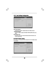
... Select Screen Select Item Change Option General Help Load Defaults Save and Exit Exit v02.54 (C) Copyright 1985-2003, American Megatrends, Inc. VIA SATA Raid Utility Use this item to [On], it will automatically activate the Numeric Lock function after boot-up. 3.5.2 Boot Device Priority In this section...54 (C) Copyright 1985-2003, American Megatrends, Inc. 35 3.5.1 Boot Settings Configuration BIOS SETUP UTILITY Boot Boot Settings Configuration Boot From Network VIA SATA RAID Utility Bootup Num-Lock [Disabled] [Enabled] [On] To enable or disable the boot from the available devices.
... Select Screen Select Item Change Option General Help Load Defaults Save and Exit Exit v02.54 (C) Copyright 1985-2003, American Megatrends, Inc. VIA SATA Raid Utility Use this item to [On], it will automatically activate the Numeric Lock function after boot-up. 3.5.2 Boot Device Priority In this section...54 (C) Copyright 1985-2003, American Megatrends, Inc. 35 3.5.1 Boot Settings Configuration BIOS SETUP UTILITY Boot Boot Settings Configuration Boot From Network VIA SATA RAID Utility Bootup Num-Lock [Disabled] [Enabled] [On] To enable or disable the boot from the available devices.
