User Guide
Page 3
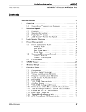
24309E-March 2002 Preliminary Information AMD Athlon™ XP Processor Model 6 Data Sheet Contents Revision History xi 1 Overview 1 1.1 QuantiSpeed™ Architecture Summary 2 2 Interface Signals 5 2.1 Overview 5 2.2 Signaling Technology 5 2.3 Push-Pull (PP) Drivers 6 2.4 AMD Athlon™ System Bus Signals 6 3 ... 23 7 Electrical Data 25 7.1 Conventions 25 7.2 Interface Signal Groupings 25 7.3 Voltage Identification (VID[4:0 26 7.4 Frequency Identification (FID[3:0 27 7.5 VCCA AC and DC Characteristics 27 7.6 Decoupling 27 7.7 VCC_CORE Characteristics 28 7.8 Absolute ...
24309E-March 2002 Preliminary Information AMD Athlon™ XP Processor Model 6 Data Sheet Contents Revision History xi 1 Overview 1 1.1 QuantiSpeed™ Architecture Summary 2 2 Interface Signals 5 2.1 Overview 5 2.2 Signaling Technology 5 2.3 Push-Pull (PP) Drivers 6 2.4 AMD Athlon™ System Bus Signals 6 3 ... 23 7 Electrical Data 25 7.1 Conventions 25 7.2 Interface Signal Groupings 25 7.3 Voltage Identification (VID[4:0 26 7.4 Frequency Identification (FID[3:0 27 7.5 VCCA AC and DC Characteristics 27 7.6 Decoupling 27 7.7 VCC_CORE Characteristics 28 7.8 Absolute ...
User Guide
Page 14
... (IPC) and high clock frequencies ■ Fully pipelined floating-point unit that increases and optimizes performance on the MMX instruction model, the AMD Athlon XP processor model 6 can be speculatively loaded. The 3DNow! Professional technology implemented in a cost-effective, industry-standard form factor. The AMD Athlon XP processor model 6 delivers excellent system performance in the AMD Athlon XP processor model 6 includes new integer...
... (IPC) and high clock frequencies ■ Fully pipelined floating-point unit that increases and optimizes performance on the MMX instruction model, the AMD Athlon XP processor model 6 can be speculatively loaded. The 3DNow! Professional technology implemented in a cost-effective, industry-standard form factor. The AMD Athlon XP processor model 6 delivers excellent system performance in the AMD Athlon XP processor model 6 includes new integer...
User Guide
Page 19
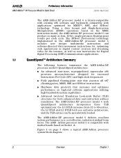
... shows the logical grouping of the processor. Logic Symbol Diagram Voltage Control Frequency Control Legacy Thermal Diode APIC Chapter 3 Logic Symbol Diagram 7 Clock Data Probe/SysCMD Request Power Management and Initialization SYSCLK SDATA[63:0]# SDATAINCLK[3:0]# SDATAOUTCLK[3:0]# SDATAINVALID# SDATAOUTVALID# SFILLVALID# SYSCLK# SADDIN[14:2]# SADDINCLK# SADDOUT[14:2]# SADDOUTCLK# AMD Athlon™ XP Processor Model 6 PROCRDY CLKFWDRST CONNECT STPCLK...
... shows the logical grouping of the processor. Logic Symbol Diagram Voltage Control Frequency Control Legacy Thermal Diode APIC Chapter 3 Logic Symbol Diagram 7 Clock Data Probe/SysCMD Request Power Management and Initialization SYSCLK SDATA[63:0]# SDATAINCLK[3:0]# SDATAOUTCLK[3:0]# SDATAINVALID# SDATAOUTVALID# SFILLVALID# SYSCLK# SADDIN[14:2]# SADDINCLK# SADDOUT[14:2]# SADDOUTCLK# AMD Athlon™ XP Processor Model 6 PROCRDY CLKFWDRST CONNECT STPCLK...
User Guide
Page 35
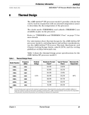
... specifications for more details. For information about thermal design for the AMD Athlon XP processor model 6, including layout and airflow considerations, see the AMD Athlon™ Processor Thermal, Mechanical, and Chassis Cooling Design Guide, order# 23794, and the cooling guidelines on the processor. Thermal Design Power Model Number Frequency (MHz) Nominal Voltage Maximum Thermal Typical Thermal Maximum Die Power...
... specifications for more details. For information about thermal design for the AMD Athlon XP processor model 6, including layout and airflow considerations, see the AMD Athlon™ Processor Thermal, Mechanical, and Chassis Cooling Design Guide, order# 23794, and the cooling guidelines on the processor. Thermal Design Power Model Number Frequency (MHz) Nominal Voltage Maximum Thermal Typical Thermal Maximum Die Power...

User Guide
Page 37
... 34, and "CLKFWDRST Pin" on page 72. 24309E-March 2002 Preliminary Information AMD Athlon™ XP Processor Model 6 Data Sheet 7 Electrical Data 7.1 Conventions The conventions used in this chapter is positive. 7.2 Interface Signal Groupings The electrical data in each signal group. Frequency FID[3:0] See "Frequency Identification (FID[3:0])" on page 27 and "FID[3:0] Pins" on page 69...
... 34, and "CLKFWDRST Pin" on page 72. 24309E-March 2002 Preliminary Information AMD Athlon™ XP Processor Model 6 Data Sheet 7 Electrical Data 7.1 Conventions The conventions used in this chapter is positive. 7.2 Interface Signal Groupings The electrical data in each signal group. Frequency FID[3:0] See "Frequency Identification (FID[3:0])" on page 27 and "FID[3:0] Pins" on page 69...
User Guide
Page 39
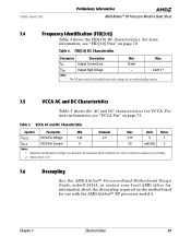
...Min Nominal Max Units Notes VVCCA VCCA Pin Voltage 2.25 2.5 2.75 V 1 IVCCA VCCA Pin Current 0 50 mA/GHz 2 Notes: 1. For more information, see "VCCA Pin" on page 70. FID[3:0] DC Characteristics Parameter Description Min Max...AC and DC Characteristics Table 5 shows the AC and DC characteristics for use with the AMD Athlon™ XP processor model 6. 24309E-March 2002 Preliminary Information AMD Athlon™ XP Processor Model 6 Data Sheet 7.4 Frequency Identification (FID[3:0]) Table 4 shows the FID[3:0] DC characteristics. For more information, see...
...Min Nominal Max Units Notes VVCCA VCCA Pin Voltage 2.25 2.5 2.75 V 1 IVCCA VCCA Pin Current 0 50 mA/GHz 2 Notes: 1. For more information, see "VCCA Pin" on page 70. FID[3:0] DC Characteristics Parameter Description Min Max...AC and DC Characteristics Table 5 shows the AC and DC characteristics for use with the AMD Athlon™ XP processor model 6. 24309E-March 2002 Preliminary Information AMD Athlon™ XP Processor Model 6 Data Sheet 7.4 Frequency Identification (FID[3:0]) Table 4 shows the FID[3:0] DC characteristics. For more information, see...

User Guide
Page 43
VCC_CORE Voltage and Current Model Number Frequency (MHz) Nominal Voltage Die Temperature ICC (Processor Current) Maximum Typical 1500+ 1333 34.3 A 30.8 A 1600+ 1400 35.9 A 32.2 A 1700+ 1467 36.6 A 32.8 A 1800+ 1533 1.75 90°C 37.7 A...Grant currents are absolute worst case currents for the AMD Athlon XP processor model 6 during the Sleep state) to the core clock grid of the processor as dictated by a value of 6003_D22Fh programmed into the Clock Control (CLK_Ctl) MSR. 5. See Figure 3, "AMD Athlon™ XP Processor Model 6 Power Management States" on page 9. ...
VCC_CORE Voltage and Current Model Number Frequency (MHz) Nominal Voltage Die Temperature ICC (Processor Current) Maximum Typical 1500+ 1333 34.3 A 30.8 A 1600+ 1400 35.9 A 32.2 A 1700+ 1467 36.6 A 32.8 A 1800+ 1533 1.75 90°C 37.7 A...Grant currents are absolute worst case currents for the AMD Athlon XP processor model 6 during the Sleep state) to the core clock grid of the processor as dictated by a value of 6003_D22Fh programmed into the Clock Control (CLK_Ctl) MSR. 5. See Figure 3, "AMD Athlon™ XP Processor Model 6 Power Management States" on page 9. ...

User Guide
Page 45
... must exhibit a suitably low closed-loop jitter bandwidth to allow the PLL to 99% of the specified frequency at a maximum rate of the specified frequency to track the jitter. Figure 10 shows a sample waveform of the AMD Athlon XP processor model 6. The -20dB attenuation point, as measured into a 10- t2 VCROSS VThreshold-AC t3 t5 Figure...
... must exhibit a suitably low closed-loop jitter bandwidth to allow the PLL to 99% of the specified frequency at a maximum rate of the specified frequency to track the jitter. Figure 10 shows a sample waveform of the AMD Athlon XP processor model 6. The -20dB attenuation point, as measured into a 10- t2 VCROSS VThreshold-AC t3 t5 Figure...

User Guide
Page 48
... = 2*fRST. 9. IOL and IOH are measured at nominal VCC_CORE. This value assumes RSTCLK period is dependent on RSTCLK frequency, divisors, Low Power mode, and core frequency. 11. In asynchronous operation, the signal must persist for this time are not guaranteed to be seen by the core....24309E-March 2002 7.12 General AC and DC Characteristics Table 13 shows the AMD Athlon XP processor model 6 AC and DC characteristics of the signal within this time to RSTCLK and RSTCK# at the same frequency, though the processor is much less than one phase. 13. Table 13. Values specified ...
... = 2*fRST. 9. IOL and IOH are measured at nominal VCC_CORE. This value assumes RSTCLK period is dependent on RSTCLK frequency, divisors, Low Power mode, and core frequency. 11. In asynchronous operation, the signal must persist for this time are not guaranteed to be seen by the core....24309E-March 2002 7.12 General AC and DC Characteristics Table 13 shows the AMD Athlon XP processor model 6 AC and DC characteristics of the signal within this time to RSTCLK and RSTCK# at the same frequency, though the processor is much less than one phase. 13. Table 13. Values specified ...

User Guide
Page 49
Values specified at the same frequency, though the processor is capable of the signal within this time to valid is much less than one phase. 13. IOL and IOH are specified with respect to ... capture. 8. See requirements 7 and 8 in normal mode operation. 10. 24309E-March 2002 Preliminary Information AMD Athlon™ XP Processor Model 6 Data Sheet Table 13. This value assumes RSTCLK period is dependent on RSTCLK frequency, divisors, Low Power mode, and core frequency. 11. This value assumes that the skew between VCC_CORE minimum and VCC_CORE maximum. 3. These are...
Values specified at the same frequency, though the processor is capable of the signal within this time to valid is much less than one phase. 13. IOL and IOH are specified with respect to ... capture. 8. See requirements 7 and 8 in normal mode operation. 10. 24309E-March 2002 Preliminary Information AMD Athlon™ XP Processor Model 6 Data Sheet Table 13. This value assumes RSTCLK period is dependent on RSTCLK frequency, divisors, Low Power mode, and core frequency. 11. This value assumes that the skew between VCC_CORE minimum and VCC_CORE maximum. 3. These are...
User Guide
Page 56
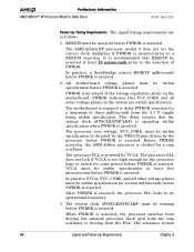
...PWROK is asserted. PWROK is asserted, the processor PLL locks to its operational frequency. 3. The processor core voltage, VCC_CORE, must be within specification as follows: 1. VCCA must be within specification. The processor PLL is powered by the processor before PWROK is asserted. After PWROK is an...by the VID[4:0] pins driven by VCCA. The AMD Athlon XP processor model 6 does not set the correct clock multiplier if PWROK is asserted. The processor PLL does not lock if VCCA is not high enough for the processor logic to switch for several milliseconds before PWROK ...
...PWROK is asserted. PWROK is asserted, the processor PLL locks to its operational frequency. 3. The processor core voltage, VCC_CORE, must be within specification as follows: 1. VCCA must be within specification. The processor PLL is powered by the processor before PWROK is asserted. After PWROK is an...by the VID[4:0] pins driven by VCCA. The AMD Athlon XP processor model 6 does not set the correct clock multiplier if PWROK is asserted. The processor PLL does not lock if VCCA is not high enough for the processor logic to switch for several milliseconds before PWROK ...
User Guide
Page 58
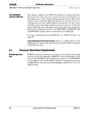
... 21902 for details of the SIP protocol. 8.2 Processor Warm Reset Requirements Northbridge Reset Pins RESET# cannot be asserted to the processor without also being asserted to the processor using the SIP protocol. Preliminary Information AMD Athlon™ XP Processor Model 6 Data Sheet 24309E-March 2002 Clock Multiplier..." on page 70. This protocol uses the PROCRDY, CONNECT, and CLKFWDRST signals, that determines the processor frequency indicated by the FID[3:0] code. Southbridges enforce a minimum assertion of 1.5 to 2.0 milliseconds. 46 Signal and Power-Up Requirements Chapter 8...
... 21902 for details of the SIP protocol. 8.2 Processor Warm Reset Requirements Northbridge Reset Pins RESET# cannot be asserted to the processor without also being asserted to the processor using the SIP protocol. Preliminary Information AMD Athlon™ XP Processor Model 6 Data Sheet 24309E-March 2002 Clock Multiplier..." on page 70. This protocol uses the PROCRDY, CONNECT, and CLKFWDRST signals, that determines the processor frequency indicated by the FID[3:0] code. Southbridges enforce a minimum assertion of 1.5 to 2.0 milliseconds. 46 Signal and Power-Up Requirements Chapter 8...

User Guide
Page 82
...Frequency Ratio 0000 11 0001 11.5 0010 12 0011 ≥ 12.51 0100 5 0101 5.5 0110 6 0111 6.5 1000 7 1001 7.5 1010 8 1011 8.5 1100 9 1101 9.5 1110 10 1111 10.5 Notes: 1. The FID[3:0] signals are pulled High on FID[3:0]. See the AMD Athlon™ and AMD... setting is asserted. Preliminary Information AMD Athlon™ XP Processor Model 6 Data Sheet 24309E-March 2002 FID[3:0] Pins FID[3] (Y3), FID[2] (Y1), FID[1] (W3), and FID[0] (W1) are the 4-bit processor clock-to the AMD Athlon™ and AMD Duron™ Processors BIOS, Software, and Debug Developers...
...Frequency Ratio 0000 11 0001 11.5 0010 12 0011 ≥ 12.51 0100 5 0101 5.5 0110 6 0111 6.5 1000 7 1001 7.5 1010 8 1011 8.5 1100 9 1101 9.5 1110 10 1111 10.5 Notes: 1. The FID[3:0] signals are pulled High on FID[3:0]. See the AMD Athlon™ and AMD... setting is asserted. Preliminary Information AMD Athlon™ XP Processor Model 6 Data Sheet 24309E-March 2002 FID[3:0] Pins FID[3] (Y3), FID[2] (Y1), FID[1] (W3), and FID[0] (W1) are the 4-bit processor clock-to the AMD Athlon™ and AMD Duron™ Processors BIOS, Software, and Debug Developers...
User Guide
Page 83
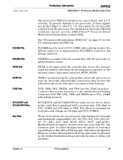
... resets the integer registers without affecting the floating-point registers or the internal caches. Chapter 10 Pin Descriptions 71 24309E-March 2002 Preliminary Information AMD Athlon™ XP Processor Model 6 Data Sheet FLUSH# Pin IGNNE# Pin INIT# Pin INTR Pin JTAG Pins K7CLKOUT and K7CLKOUT# Pins Key Pins The... these pins directly to VSS. If a debug connector is implemented, FLUSH# is an input from the processor. See "Frequency Identification (FID[3:0])" on page 27 for the DC characteristics for two to three inches and then terminated with a resistor pair: 100 ohms to VCC_CORE ...
... resets the integer registers without affecting the floating-point registers or the internal caches. Chapter 10 Pin Descriptions 71 24309E-March 2002 Preliminary Information AMD Athlon™ XP Processor Model 6 Data Sheet FLUSH# Pin IGNNE# Pin INIT# Pin INTR Pin JTAG Pins K7CLKOUT and K7CLKOUT# Pins Key Pins The... these pins directly to VSS. If a debug connector is implemented, FLUSH# is an input from the processor. See "Frequency Identification (FID[3:0])" on page 27 for the DC characteristics for two to three inches and then terminated with a resistor pair: 100 ohms to VCC_CORE ...