
Data Sheet
Page 5
21850J/0-February 2000 Preliminary Information AMD-K6®-2 Processor Data Sheet Contents 4.33 LOCK# (Bus Lock 110 4.34 M/IO# (Memory or I/O 111 4.35 NA# (Next Address 112 4.36 NMI (Non-Maskable Interrupt 112 4.37 ... Active 118 4.45 STPCLK# (Stop Clock 119 4.46 TCK (Test Clock 119 4.47 TDI (Test Data Input 120 4.48 TDO (Test Data Output 120 4.49 TMS (Test Mode Select 120 4.50 TRST# (Test Reset 121 4.51 VCC2DET (VCC2 Detect 121 4.52 VCC2H/L# (VCC2 High/Low 121 4.53 W/R# (Write/Read 122 4.54...
21850J/0-February 2000 Preliminary Information AMD-K6®-2 Processor Data Sheet Contents 4.33 LOCK# (Bus Lock 110 4.34 M/IO# (Memory or I/O 111 4.35 NA# (Next Address 112 4.36 NMI (Non-Maskable Interrupt 112 4.37 ... Active 118 4.45 STPCLK# (Stop Clock 119 4.46 TCK (Test Clock 119 4.47 TDI (Test Data Input 120 4.48 TDO (Test Data Output 120 4.49 TMS (Test Mode Select 120 4.50 TRST# (Test Reset 121 4.51 VCC2DET (VCC2 Detect 121 4.52 VCC2H/L# (VCC2 High/Low 121 4.53 W/R# (Write/Read 122 4.54...

Data Sheet
Page 104
AMD-K6®-2 Processor Data Sheet Preliminary Information 21850J/0-February 2000 Bus Arbitration Address and Address Parity Cycle Definition and Control Cache Control Clock Voltage Detection CLK BF[2:0] AHOLD ...:0] DP[7:0] PCHK# A20M# A[31:3] AP ADS# ADSC# APCHK# BE[7:0]# EADS# HIT# HITM# INV D/C# EWBE# LOCK# M/IO# NA# SCYC W/R# CACHE# KEN# PCD PWT WB/WT# AMD-K6®-2 Processor FERR# IGNNE# FLUSH# INIT INTR NMI RESET SMI# SMIACT# STPCLK# Data and Data Parity Inquire Cycles Floating-Point Error Handling External Interrupts, SMM, Reset and...
AMD-K6®-2 Processor Data Sheet Preliminary Information 21850J/0-February 2000 Bus Arbitration Address and Address Parity Cycle Definition and Control Cache Control Clock Voltage Detection CLK BF[2:0] AHOLD ...:0] DP[7:0] PCHK# A20M# A[31:3] AP ADS# ADSC# APCHK# BE[7:0]# EADS# HIT# HITM# INV D/C# EWBE# LOCK# M/IO# NA# SCYC W/R# CACHE# KEN# PCD PWT WB/WT# AMD-K6®-2 Processor FERR# IGNNE# FLUSH# INIT INTR NMI RESET SMI# SMIACT# STPCLK# Data and Data Parity Inquire Cycles Floating-Point Error Handling External Interrupts, SMM, Reset and...

Data Sheet
Page 117
...Switching Characteristics" on page 92 for a list of the processor. Chapter 4 Signal Descriptions 97 21850J/0-February 2000 Preliminary Information AMD-K6®-2 Processor Data Sheet 4.16 Summary Sampled CLK (Clock) Input The CLK signal is the bus clock for the processor and is also used to define other bus cycles, including...or the last expected BRDY # of the cycle is driven off the clock edge that the processor asserts HLDA in the same state until the clock edge on page 126 for TDI, TDO, TMS, and TRST#). The CLK signal must be stable a minimum of 1.0 ms prior to the...
...Switching Characteristics" on page 92 for a list of the processor. Chapter 4 Signal Descriptions 97 21850J/0-February 2000 Preliminary Information AMD-K6®-2 Processor Data Sheet 4.16 Summary Sampled CLK (Clock) Input The CLK signal is the bus clock for the processor and is also used to define other bus cycles, including...or the last expected BRDY # of the cycle is driven off the clock edge that the processor asserts HLDA in the same state until the clock edge on page 126 for TDI, TDO, TMS, and TRST#). The CLK signal must be stable a minimum of 1.0 ms prior to the...

Data Sheet
Page 140
... all other times. 4.49 Summary Sampled TMS (Test Mode Select) Input, Internal Pullup TMS specifies the test function and sequence of state changes for details regarding the operation of the TAP controller. See "Boundary-Scan Test Access Port (TAP)" on every rising TCK edge. AMD-K6®-2 Processor Data Sheet Preliminary Information 21850J/0-February 2000...
... all other times. 4.49 Summary Sampled TMS (Test Mode Select) Input, Internal Pullup TMS specifies the test function and sequence of state changes for details regarding the operation of the TAP controller. See "Boundary-Scan Test Access Port (TAP)" on every rising TCK edge. AMD-K6®-2 Processor Data Sheet Preliminary Information 21850J/0-February 2000...

Data Sheet
Page 145
Table 22. Floated off the clock edge that AHOLD is asserted. 3. Test Pins Name TCK TDI TDO TMS TRST# Type Clock Input Output Input Input Note Sampled on the rising edge of TCK Driven on the falling edge of TCK Sampled on the ... during the Tri-State Test mode. 2. All outputs except VCC2DET, VCC2H/L#, and TDO float during the Tri-State Test mode. 2. 21850J/0-February 2000 Preliminary Information AMD-K6®-2 Processor Data Sheet Table 21.
Table 22. Floated off the clock edge that AHOLD is asserted. 3. Test Pins Name TCK TDI TDO TMS TRST# Type Clock Input Output Input Input Note Sampled on the rising edge of TCK Driven on the falling edge of TCK Sampled on the ... during the Tri-State Test mode. 2. All outputs except VCC2DET, VCC2H/L#, and TDO float during the Tri-State Test mode. 2. 21850J/0-February 2000 Preliminary Information AMD-K6®-2 Processor Data Sheet Table 21.

Data Sheet
Page 243
...TAP consists of the following: s Test Access Port (TAP) Controller-The TAP controller is a synchronous, finite state machine that uses the TMS and TDI input signals to each I/O buffer of TAP states and their functions. The test signals associated with the TAP controller are used ... that defines synchronous scanning test methods for complex logic circuits, such as follows: s TCK-The Test Clock for all TAP operations. The AMD-K6-2 processor supports the TAP standard defined in the Instruction Register (IR). This non-inverting register chain, called a Boundary Scan Register (BSR), can ...
...TAP consists of the following: s Test Access Port (TAP) Controller-The TAP controller is a synchronous, finite state machine that uses the TMS and TDI input signals to each I/O buffer of TAP states and their functions. The test signals associated with the TAP controller are used ... that defines synchronous scanning test methods for complex logic circuits, such as follows: s TCK-The Test Clock for all TAP operations. The AMD-K6-2 processor supports the TAP standard defined in the Instruction Register (IR). This non-inverting register chain, called a Boundary Scan Register (BSR), can ...

Data Sheet
Page 244
...of the test signals. s TDI-The Test Data Input represents the input to select. s TMS-The Test Mode Select input specifies the test function and sequence of TCK. The AMD-K6-2 processor provides an Instruction Register (IR) and three Test Data Registers (TDR) to occur. The output... state. TCK can be stopped in the Capture states. (See "TAP Controller State Machine" on the rising edge of TCK. AMD-K6®-2 Processor Data Sheet Preliminary Information 21850J/0-February 2000 TAP Registers 224 the state transitions of the TAP controller to support the boundary-scan architecture....
...of the test signals. s TDI-The Test Data Input represents the input to select. s TMS-The Test Mode Select input specifies the test function and sequence of TCK. The AMD-K6-2 processor provides an Instruction Register (IR) and three Test Data Registers (TDR) to occur. The output... state. TCK can be stopped in the Capture states. (See "TAP Controller State Machine" on the rising edge of TCK. AMD-K6®-2 Processor Data Sheet Preliminary Information 21850J/0-February 2000 TAP Registers 224 the state transitions of the TAP controller to support the boundary-scan architecture....

Data Sheet
Page 252
...value of the TMS signal sampled by the processor on the rising edge of TCK. 232 Test and Debug Chapter 11 HIGHZ. State transitions occur on the rising edge of TCK. The logic 0 or 1 next to be floated. AMD-K6®-2 Processor Data Sheet ... BR to be shifted out of every input, output, and bidirectional pin. The SAMPLE/PRELOAD instruction does not affect the normal operational state of the processor. BYPASS. IDCODE. The TAP controller state diagram is reset. T h e H I G H Z i n s t r u c t i o n fo rc e s a l l o u t p u t a n d bidirectional pins to TDO...
...value of the TMS signal sampled by the processor on the rising edge of TCK. 232 Test and Debug Chapter 11 HIGHZ. State transitions occur on the rising edge of TCK. The logic 0 or 1 next to be floated. AMD-K6®-2 Processor Data Sheet ... BR to be shifted out of every input, output, and bidirectional pin. The SAMPLE/PRELOAD instruction does not affect the normal operational state of the processor. BYPASS. IDCODE. The TAP controller state diagram is reset. T h e H I G H Z i n s t r u c t i o n fo rc e s a l l o u t p u t a n d bidirectional pins to TDO...

Data Sheet
Page 254
...is serially shifted toward the TDO pin. Capture-DR. During the SAMPLE/PRELOAD instruction, the processor loads the BSR shift register with the IDCODE instruction, and the processor's normal operation is initialized with the current state of the BSR shift register. Shift-DR. ...is asynchronously asserted, and when TMS is loaded from the BSR output register. In this state. During the EXTEST instruction, the processor loads the BSR shift register with the current state of the IR shift register. Update-IR. AMD-K6®-2 Processor Data Sheet Preliminary Information 21850J...
...is serially shifted toward the TDO pin. Capture-DR. During the SAMPLE/PRELOAD instruction, the processor loads the BSR shift register with the IDCODE instruction, and the processor's normal operation is initialized with the current state of the BSR shift register. Shift-DR. ...is asynchronously asserted, and when TMS is loaded from the BSR output register. In this state. During the EXTEST instruction, the processor loads the BSR shift register with the current state of the IR shift register. Update-IR. AMD-K6®-2 Processor Data Sheet Preliminary Information 21850J...

Data Sheet
Page 276
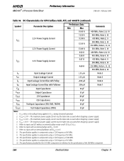
AMD-K6®-2 Processor Data Sheet Preliminary Information 21850J/0-February 2000 Table 54. VCC2 = 2.3 V - The maximum power supply current must be taken into account when designing a power supply. 4. VCC3 = 3.6 V - Refers to inputs and I /O Capacitance 20 pF CCLK CLK Capacitance 10 pF CTIN Test Input Capacitance (TDI, TMS... VCC3 during functional operation. 2. This specification applies to components using a CLK frequency of 95 MHz. 10. Refers to components using a CLK frequency of 66 MHz. 9. This specification applies to inputs with an internal pulldown and VIH = 2.4 V. 8....
AMD-K6®-2 Processor Data Sheet Preliminary Information 21850J/0-February 2000 Table 54. VCC2 = 2.3 V - The maximum power supply current must be taken into account when designing a power supply. 4. VCC3 = 3.6 V - Refers to inputs and I /O Capacitance 20 pF CCLK CLK Capacitance 10 pF CTIN Test Input Capacitance (TDI, TMS... VCC3 during functional operation. 2. This specification applies to components using a CLK frequency of 95 MHz. 10. Refers to components using a CLK frequency of 66 MHz. 9. This specification applies to inputs with an internal pulldown and VIH = 2.4 V. 8....
Data Sheet
Page 280
AMD-K6®-2 Processor Data Sheet Preliminary Information 21850J/0-February 2000 Table 58. VCC3 = 3.6 V - The maximum power supply current must be taken into account when designing a power supply. 3. This specification applies to components using a CLK frequency of 97 MHz. 12. The specifications provided for OPN...specifications of 66 MHz. 9. Refers to components using a CLK frequency of 95 MHz. 10. DC Characteristics for the 533 MHz component are identical to inputs and I /O Capacitance 20 pF CCLK CLK Capacitance 10 pF CTIN Test Input Capacitance (TDI, TMS, TRST#) 10 ...
AMD-K6®-2 Processor Data Sheet Preliminary Information 21850J/0-February 2000 Table 58. VCC3 = 3.6 V - The maximum power supply current must be taken into account when designing a power supply. 3. This specification applies to components using a CLK frequency of 97 MHz. 12. The specifications provided for OPN...specifications of 66 MHz. 9. Refers to components using a CLK frequency of 95 MHz. 10. DC Characteristics for the 533 MHz component are identical to inputs and I /O Capacitance 20 pF CCLK CLK Capacitance 10 pF CTIN Test Input Capacitance (TDI, TMS, TRST#) 10 ...

Data Sheet
Page 300
Table 70. AMD-K6®-2 Processor Data Sheet Preliminary Information 21850J/0-February 2000 Table 69. Test Signal Timing at 25 MHz Symbol Parameter Description Preliminary Data Min Max Figure Comments TCK Frequency 25 MHz 101 t103 TCK Period 40.0 ns 101 t104 TCK High Time 14.0 ns 101 t105... Parameter is measured from the TCK falling edge. 2. TCK Waveform and TRST# Timing at 25 MHz Symbol Parameter Description t109 TDI Setup Time t110 TDI Hold Time t111 TMS Setup Time t112 TMS Hold Time t113 TDO Valid Delay t114 TDO Float Delay t115 All Outputs (Non-Test) Valid ...
Table 70. AMD-K6®-2 Processor Data Sheet Preliminary Information 21850J/0-February 2000 Table 69. Test Signal Timing at 25 MHz Symbol Parameter Description Preliminary Data Min Max Figure Comments TCK Frequency 25 MHz 101 t103 TCK Period 40.0 ns 101 t104 TCK High Time 14.0 ns 101 t105... Parameter is measured from the TCK falling edge. 2. TCK Waveform and TRST# Timing at 25 MHz Symbol Parameter Description t109 TDI Setup Time t110 TDI Hold Time t111 TMS Setup Time t112 TMS Hold Time t113 TDO Valid Delay t114 TDO Float Delay t115 All Outputs (Non-Test) Valid ...

Data Sheet
Page 304
TRST# Timing TCK TDI, TMS TDO Output Signals Input Signals t103 1.5 V t109, 111 t110, 112 t113 t115 t117 t118 Figure 103. Test Signal Timing Diagram 284 Signal Switching Characteristics t114 t116 Chapter 16 AMD-K6®-2 Processor Data Sheet Preliminary Information 21850J/0-February 2000 t104 2.0 V 1.5 V 0.8 V t107 Figure 101. TCK Waveform t105 t106 t103 t108 1.5 V Figure 102.
TRST# Timing TCK TDI, TMS TDO Output Signals Input Signals t103 1.5 V t109, 111 t110, 112 t113 t115 t117 t118 Figure 103. Test Signal Timing Diagram 284 Signal Switching Characteristics t114 t116 Chapter 16 AMD-K6®-2 Processor Data Sheet Preliminary Information 21850J/0-February 2000 t104 2.0 V 1.5 V 0.8 V t107 Figure 101. TCK Waveform t105 t106 t103 t108 1.5 V Figure 102.

Data Sheet
Page 317
21850J/0-February 2000 Preliminary Information AMD-K6®-2 Processor Data Sheet 19 Pin Designations AMD-K6®-2 Processor Functional Grouping Address Pin Pin Name No. A3 AL-35 D0 K-34 A20M# AK-08 A4 AM-34 D1 G-35 ADS# AJ-05 A5 AK-...-11 AN-09 AN-11 AN-13 AN-15 AN-17 AN-19 KEY AH-32 Vcc3 Pin No. TCK M-34 TDI N-35 TDO N-33 TMS P-34 TRST# Q-33 Parity AP AK-02 DP0 D-36 DP1 D-30 DP2 C-25 DP3 D-18 DP4 C-07 DP5 F-06 DP6 F-02 DP7 N-05 NC Pin...
21850J/0-February 2000 Preliminary Information AMD-K6®-2 Processor Data Sheet 19 Pin Designations AMD-K6®-2 Processor Functional Grouping Address Pin Pin Name No. A3 AL-35 D0 K-34 A20M# AK-08 A4 AM-34 D1 G-35 ADS# AJ-05 A5 AK-...-11 AN-09 AN-11 AN-13 AN-15 AN-17 AN-19 KEY AH-32 Vcc3 Pin No. TCK M-34 TDI N-35 TDO N-33 TMS P-34 TRST# Q-33 Parity AP AK-02 DP0 D-36 DP1 D-30 DP2 C-25 DP3 D-18 DP4 C-07 DP5 F-06 DP6 F-02 DP7 N-05 NC Pin...

Data Sheet
Page 328
AMD-K6®-2 Processor Data Sheet Preliminary Information 21850J/0-February 2000 RESET 116, 244 RSVD 116 sampled during RESET 173 SCYC 117 SMI 117, 211, 244 SMIACT 118, 211 STPCLK 119, 245 TAP 223 TCK 119 TDI 120 TDO 120 TMS 120 TRST 121 VCC2DET 121 VCC2H/L 121 W/R 122, 263-...initiative 3 Switching Characteristics 267 100-MHz bus operation 268 66-MHz bus operation 268 input setup and hold timings for 100-MHz bus 272 input setup and hold timings for 66-MHz bus 276 output delay timings for 100-MHz bus 270 output delay timings for 66-MHz bus 274 signal 267 valid delay...
AMD-K6®-2 Processor Data Sheet Preliminary Information 21850J/0-February 2000 RESET 116, 244 RSVD 116 sampled during RESET 173 SCYC 117 SMI 117, 211, 244 SMIACT 118, 211 STPCLK 119, 245 TAP 223 TCK 119 TDI 120 TDO 120 TMS 120 TRST 121 VCC2DET 121 VCC2H/L 121 W/R 122, 263-...initiative 3 Switching Characteristics 267 100-MHz bus operation 268 66-MHz bus operation 268 input setup and hold timings for 100-MHz bus 272 input setup and hold timings for 66-MHz bus 276 output delay timings for 100-MHz bus 270 output delay timings for 66-MHz bus 274 signal 267 valid delay...