
Installation Guide
Page 10
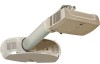
... Gas Shock Step 1. Use a rubber mallet to secure plate. Align holes and install four screws. Step 2. Remove the two (2) M10 x 35mm set screw mounting points. Step 3. Step 7. The cable ports of the support poles must face the back of the base columns to secure the support poles to the... x 20mm to gently hammer the gas shock base into place between support poles. Key: A=Model SCP716, B=Model SCP712, C=Model SCP715/717/740. 10 Back Plate 716 712 AB 715/717/740 C © 3M 2010. Step 4. Slide the unit forward until it is resting on the base with the support...
... Gas Shock Step 1. Use a rubber mallet to secure plate. Align holes and install four screws. Step 2. Remove the two (2) M10 x 35mm set screw mounting points. Step 3. Step 7. The cable ports of the support poles must face the back of the base columns to secure the support poles to the... x 20mm to gently hammer the gas shock base into place between support poles. Key: A=Model SCP716, B=Model SCP712, C=Model SCP715/717/740. 10 Back Plate 716 712 AB 715/717/740 C © 3M 2010. Step 4. Slide the unit forward until it is resting on the base with the support...