
Getting Started Guide
Page 3
...Redundant Power System Socket 19 Console Port 20 Expansion Module Slot 20 Default Settings 20 2 INSTALLING THE SWITCH Package Contents 22 Choosing a Suitable Site 22 Rack-mounting 23 Placing Units On Top of Hardware Features 13 Switch - Front View Detail 14 100/1000BASE-T and ... Ports 16 1000BASE-SX Ports 16 GBIC Ports 16 LEDs 17 Switch - CONTENTS ABOUT THIS GUIDE Conventions 8 Related Documentation 9 Accessing Online Documentation 9 Documentation Comments 10 1 INTRODUCING THE SUPERSTACK 3 SWITCH 4900 FAMILY About the Switches 12 Summary of Each Other 24 Creating an XRN Distributed Fabric 24...
...Redundant Power System Socket 19 Console Port 20 Expansion Module Slot 20 Default Settings 20 2 INSTALLING THE SWITCH Package Contents 22 Choosing a Suitable Site 22 Rack-mounting 23 Placing Units On Top of Hardware Features 13 Switch - Front View Detail 14 100/1000BASE-T and ... Ports 16 1000BASE-SX Ports 16 GBIC Ports 16 LEDs 17 Switch - CONTENTS ABOUT THIS GUIDE Conventions 8 Related Documentation 9 Accessing Online Documentation 9 Documentation Comments 10 1 INTRODUCING THE SUPERSTACK 3 SWITCH 4900 FAMILY About the Switches 12 Summary of Each Other 24 Creating an XRN Distributed Fabric 24...
Getting Started Guide
Page 9
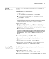
..., and known problems. ■ Implementation Guide This guide contains information on the CD-ROM that accompanies the Switch. ■ Management Interface Reference Guide This guide provides detailed information about the web interface and command line interface...Documentation accompanying the Advanced Redundant Power System. ■ Documentation accompanying the Expansion Modules. ■ Documentation accompanying 3Com Network Supervisor. Accessing Online Documentation The CD-ROM supplied with your Switch contains the following : ■ Management Quick Reference Guide This guide contains:...
..., and known problems. ■ Implementation Guide This guide contains information on the CD-ROM that accompanies the Switch. ■ Management Interface Reference Guide This guide provides detailed information about the web interface and command line interface...Documentation accompanying the Advanced Redundant Power System. ■ Documentation accompanying the Expansion Modules. ■ Documentation accompanying 3Com Network Supervisor. Accessing Online Documentation The CD-ROM supplied with your Switch contains the following : ■ Management Quick Reference Guide This guide contains:...

Getting Started Guide
Page 11
... about the Switch 4900, 4900 SX, 4924 and 4950 and how they can be used in the Switch 4900 Family is the same unless otherwise stated. ■ About the Switches ■ Summary of Hardware Features ■ Switch - The information for all the Switches in your ... Unit Information Label ■ Power Socket ■ Redundant Power System Socket ■ Console Port ■ Expansion Module Slot ■ Default Settings 1 INTRODUCING THE SUPERSTACK 3 SWITCH 4900 FAMILY This chapter contains introductory information about the hardware. Front View Detail ■ 100/1000BASE-T and 10/...
... about the Switch 4900, 4900 SX, 4924 and 4950 and how they can be used in the Switch 4900 Family is the same unless otherwise stated. ■ About the Switches ■ Summary of Hardware Features ■ Switch - The information for all the Switches in your ... Unit Information Label ■ Power Socket ■ Redundant Power System Socket ■ Console Port ■ Expansion Module Slot ■ Default Settings 1 INTRODUCING THE SUPERSTACK 3 SWITCH 4900 FAMILY This chapter contains introductory information about the hardware. Front View Detail ■ 100/1000BASE-T and 10/...

Getting Started Guide
Page 14
front view Front View Detail Figure 1 Switch 4900 - 14 CHAPTER 1: INTRODUCING THE SUPERSTACK 3 SWITCH 4900 FAMILY Switch - front view 1x 3C17700 Status Module Unit green = 1000 Mbps yellow = 100 Mbps on = enabled, link OK flashing = disabled Packet 1 2 3 4 5 6 7 8 9 10 11 12 6x Status 1 2 3 4 5 6 7 8 9 10 11 12 12 34 Power/Self Test 7x Layer 3 Switch 4900 12x 3C17700 SuperStack 3 Port Status LEDs 100BASE-TX / 1000BASE-T Ports Module Status LEDs Power / Self Test LED and Layer 3 LED Unit LEDs 100BASE-TX / 1000BASE-T Ports Figure 2 Switch 4900 SX -
front view Front View Detail Figure 1 Switch 4900 - 14 CHAPTER 1: INTRODUCING THE SUPERSTACK 3 SWITCH 4900 FAMILY Switch - front view 1x 3C17700 Status Module Unit green = 1000 Mbps yellow = 100 Mbps on = enabled, link OK flashing = disabled Packet 1 2 3 4 5 6 7 8 9 10 11 12 6x Status 1 2 3 4 5 6 7 8 9 10 11 12 12 34 Power/Self Test 7x Layer 3 Switch 4900 12x 3C17700 SuperStack 3 Port Status LEDs 100BASE-TX / 1000BASE-T Ports Module Status LEDs Power / Self Test LED and Layer 3 LED Unit LEDs 100BASE-TX / 1000BASE-T Ports Figure 2 Switch 4900 SX -
Getting Started Guide
Page 17
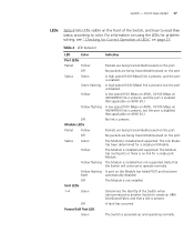
..., see "Checking for Correct Operation of LEDs" on 4900 SX.) No link is present. A low speed (100 Mbps on 4900, 10/100 Mbps on 4924/4950) link is present, and the port is enabled. (Not applicable on 4900 SX.) A low speed (100 Mbps on 4900, 10/100 Mbps on... (1000 Mbps) link is present, and the port is powered-up and operating normally. Determines the identity of the Switch, and how to read their status according to operate normally. The Module is present. Packets are being transmitted/received on the port. Table 4 LED behavior LED Color Port LEDs Packet Yellow...
..., see "Checking for Correct Operation of LEDs" on 4900 SX.) No link is present. A low speed (100 Mbps on 4900, 10/100 Mbps on 4924/4950) link is present, and the port is enabled. (Not applicable on 4900 SX.) A low speed (100 Mbps on 4900, 10/100 Mbps on... (1000 Mbps) link is present, and the port is powered-up and operating normally. Determines the identity of the Switch, and how to read their status according to operate normally. The Module is present. Packets are being transmitted/received on the port. Table 4 LED behavior LED Color Port LEDs Packet Yellow...
Getting Started Guide
Page 20
...CHAPTER 1: INTRODUCING THE SUPERSTACK 3 SWITCH 4900 FAMILY Console Port The console port allows you initialize one of the Switch units, it is set to auto-baud (up to a maximum of 19200 baud), 8 data bits, no other Switches on the range of Expansion Modules supported by tightening all... screws with an IP address in the range 169.254.1.0 to 169.254.254.255. Contact your Switch. Notify and unfilter All ports belong to the untagged Default VLAN (VLAN 1) IGMP filtering enabled Enabled Disabled per port Switch 4900, 4924, and 4950: Enabled Switch...
...CHAPTER 1: INTRODUCING THE SUPERSTACK 3 SWITCH 4900 FAMILY Console Port The console port allows you initialize one of the Switch units, it is set to auto-baud (up to a maximum of 19200 baud), 8 data bits, no other Switches on the range of Expansion Modules supported by tightening all... screws with an IP address in the range 169.254.1.0 to 169.254.254.255. Contact your Switch. Notify and unfilter All ports belong to the untagged Default VLAN (VLAN 1) IGMP filtering enabled Enabled Disabled per port Switch 4900, 4924, and 4950: Enabled Switch...

Getting Started Guide
Page 25
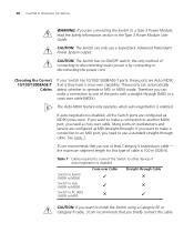
...Kits or GBIC module. ■ The maximum number of Switch units that can interconnect your network supplier for further information. ■ SuperStack 3 Switch 4900 Family GBIC Module (3C17714) operating in separate racks you can also be fitted. ■ The XRN Interconnect Module and the GBIC Module are NOT ... interconnected is two. ■ Both Switches must have an Fabric Interconnect extended up to 70 Km (43.5 miles) between the units, if necessary (dependant upon GBIC transceiver type). Should you wish to be located on the 3Com Web site. consists of the following methods...
...Kits or GBIC module. ■ The maximum number of Switch units that can interconnect your network supplier for further information. ■ SuperStack 3 Switch 4900 Family GBIC Module (3C17714) operating in separate racks you can also be fitted. ■ The XRN Interconnect Module and the GBIC Module are NOT ... interconnected is two. ■ Both Switches must have an Fabric Interconnect extended up to 70 Km (43.5 miles) between the units, if necessary (dependant upon GBIC transceiver type). Should you wish to be located on the 3Com Web site. consists of the following methods...

Getting Started Guide
Page 26
... before you will be assigned the identity of Unit 2. ■ When the Switch units are in an XRN Distributed Fabric created using a GBIC Module you interconnect to which the GBIC Module is not possible to interconnect the SuperStack 3 Switch 4900 Family and 3Com Switch 40x0 units with the yellow cable end will need GMS software version 4.0 or...
... before you will be assigned the identity of Unit 2. ■ When the Switch units are in an XRN Distributed Fabric created using a GBIC Module you interconnect to which the GBIC Module is not possible to interconnect the SuperStack 3 Switch 4900 Family and 3Com Switch 40x0 units with the yellow cable end will need GMS software version 4.0 or...

Getting Started Guide
Page 27
... cord into your power outlet. Table 6 Power/Self Test LED Colors Color Green Yellow Off State The Switch is not receiving power. For full redundancy, the unit requires two Type 3 Power Modules combined using a Type 3 Y-Cable (part number 3C16077). Table 6 shows possible colors for Correct During... On Self Test (POST) because of an internal problem. If there is operating correctly. Connecting a You can connect a SuperStack 3 Advanced Redundant Power System to your Switch if a power supply failure occurs. When the POST has completed, check the Power/Self Test LED to make sure that ...
... cord into your power outlet. Table 6 Power/Self Test LED Colors Color Green Yellow Off State The Switch is not receiving power. For full redundancy, the unit requires two Type 3 Power Modules combined using a Type 3 Y-Cable (part number 3C16077). Table 6 shows possible colors for Correct During... On Self Test (POST) because of an internal problem. If there is operating correctly. Connecting a You can connect a SuperStack 3 Advanced Redundant Power System to your Switch if a power supply failure occurs. When the POST has completed, check the Power/Self Test LED to make sure that ...
Getting Started Guide
Page 28
...negotiation is by connecting or disconnecting the power cord. Table 7 Cables required to connect the Switch to other devices if auto-negotiation is disabled Switch to Switch (MDIX to MDIX) Switch to Hub (MDIX to MDIX) Switch to PC (NIC) (MDIX to one of cable is they have a cross-over ...to operate in the Type 3 Power Module User Guide. If you want to make a connection to MDI) Cross-over ). See Table 7. 3Com recommends that you briefly connect the cable Many ports on workstations and servers are Auto-MDIX, that you use a SuperStack Advanced Redundant Power System output. the...
...negotiation is by connecting or disconnecting the power cord. Table 7 Cables required to connect the Switch to other devices if auto-negotiation is disabled Switch to Switch (MDIX to MDIX) Switch to Hub (MDIX to MDIX) Switch to PC (NIC) (MDIX to one of cable is they have a cross-over ...to operate in the Type 3 Power Module User Guide. If you want to make a connection to MDI) Cross-over ). See Table 7. 3Com recommends that you briefly connect the cable Many ports on workstations and servers are Auto-MDIX, that you use a SuperStack Advanced Redundant Power System output. the...
Getting Started Guide
Page 55
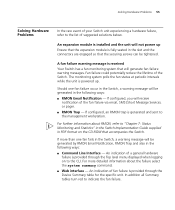
...than one fan failure occur in the Switch, a warning message will be tightened. An indication of fan failure is powered up Ensure that the expansion module is generated and sent to "Chapter 7: Status Monitoring and Statistics" in the Switch Implementation Guide supplied in the following ways...: ■ RMON Email Notification - Should one fan fails in the Switch, a warning message will be ...
...than one fan failure occur in the Switch, a warning message will be tightened. An indication of fan failure is powered up Ensure that the expansion module is generated and sent to "Chapter 7: Status Monitoring and Statistics" in the Switch Implementation Guide supplied in the following ways...: ■ RMON Email Notification - Should one fan fails in the Switch, a warning message will be ...

Getting Started Guide
Page 61
... unshielded data cables with a suitable tool. WARNING: If you are connecting the Switch to the unit and easily accessible. WARNING: France and Peru only: This unit cannot be used in the Type 3 Power Module User Guide. The rack mount kits alone are only maintained if the equipment to... which is connected also operates under SELV (Safety Extra Low Voltage) conditions according to the console port of the switch. WARNING: This unit operates under SELV ...
... unshielded data cables with a suitable tool. WARNING: If you are connecting the Switch to the unit and easily accessible. WARNING: France and Peru only: This unit cannot be used in the Type 3 Power Module User Guide. The rack mount kits alone are only maintained if the equipment to... which is connected also operates under SELV (Safety Extra Low Voltage) conditions according to the console port of the switch. WARNING: This unit operates under SELV ...