Getting Started Guide
Page 22
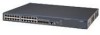
The port operates in .) Weight The port fails the POST. No link is present. System Specifications of the Switch 4800G Series Table 7 System specifications of the Switch 4800G 48-Port LED Mark Status SFP port status LED (100 Mbps) Speed Yellow Duplex Flashing yellow ...fails the POST. 22 CHAPTER 1: PRODUCT OVERVIEW Table 6 Description of LEDs on the front panel of the Switch 4800G Item Switch 4800G 24-Port Switch 4800G PWR 48-Port Switch 4800G PWR 24-Port Switch 4800G 24-Port SFP Switch 4800G 48-Port Physical dimensions (H × W × D) 43.6 × 440 × 300 mm ...
The port operates in .) Weight The port fails the POST. No link is present. System Specifications of the Switch 4800G Series Table 7 System specifications of the Switch 4800G 48-Port LED Mark Status SFP port status LED (100 Mbps) Speed Yellow Duplex Flashing yellow ...fails the POST. 22 CHAPTER 1: PRODUCT OVERVIEW Table 6 Description of LEDs on the front panel of the Switch 4800G Item Switch 4800G 24-Port Switch 4800G PWR 48-Port Switch 4800G PWR 24-Port Switch 4800G 24-Port SFP Switch 4800G 48-Port Physical dimensions (H × W × D) 43.6 × 440 × 300 mm ...
Getting Started Guide
Page 29
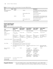
...guide rails The selection of installation methods depends on a mounting screw of the 3Com switch chassis is greater than 300 mm (11.8 in), the front mounting ears only secure the switch rather than bear its weight. ■ Guide rails purchased from your sales agent to Figure 17 shows... the appearance of a switch is intact. Introduction to maintain the switch, you must ensure that the dismantlement-preventive seal on the...
...guide rails The selection of installation methods depends on a mounting screw of the 3Com switch chassis is greater than 300 mm (11.8 in), the front mounting ears only secure the switch rather than bear its weight. ■ Guide rails purchased from your sales agent to Figure 17 shows... the appearance of a switch is intact. Introduction to maintain the switch, you must ensure that the dismantlement-preventive seal on the...

Getting Started Guide
Page 34
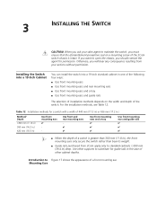
34 CHAPTER 3: INSTALLING THE SWITCH Figure 24 Fix front and rear mounting ears Front square-holed bracket Rear panel Screw 1 Front mounting ear Rear mounting ear Screw 2 Rear square-holed bracket Screw 1: Used to bear the weight Screw 2: Used to fix rear mounting ears to rear brackets After the switch is pushed into the cabinet, ensure that the upper edge of rear mounting ears is tightly contacted with the load-bearing screw, as shown in Figure 25.
34 CHAPTER 3: INSTALLING THE SWITCH Figure 24 Fix front and rear mounting ears Front square-holed bracket Rear panel Screw 1 Front mounting ear Rear mounting ear Screw 2 Rear square-holed bracket Screw 1: Used to bear the weight Screw 2: Used to fix rear mounting ears to rear brackets After the switch is pushed into the cabinet, ensure that the upper edge of rear mounting ears is tightly contacted with the load-bearing screw, as shown in Figure 25.