
User Manual
Page 1
DUA1740-0AAA01 Published May 2003 Switch 3812 and Switch 3824 Getting Started Guide 3C17401 3C17400 http://www.3com.com/ Part No.
DUA1740-0AAA01 Published May 2003 Switch 3812 and Switch 3824 Getting Started Guide 3C17401 3C17400 http://www.3com.com/ Part No.

User Manual
Page 3
... Accessing Online Documentation 10 Documentation Comments 10 Product Registration 11 1 INTRODUCING THE SWITCH 3812 AND SWITCH 3824 About the Switch 14 Summary of LEDs 23 Rear View Detail 17 Power Socket 17 Default Settings 18 2 INSTALLING THE SWITCH Package Contents 20 Choosing a Suitable Site 20 Rack-mounting 21 Placing Units ...On Top of Each Other 23 The Power-up Sequence 23 Powering-up the Switch 23 Checking for Correct Operation of Hardware Features 14 Switch - Front View Detail 15 10BASE-T/ 100BASE-TX/ 1000BASE-T Ports 15 SFP Ports 16 LEDs 16 Console Port...
... Accessing Online Documentation 10 Documentation Comments 10 Product Registration 11 1 INTRODUCING THE SWITCH 3812 AND SWITCH 3824 About the Switch 14 Summary of LEDs 23 Rear View Detail 17 Power Socket 17 Default Settings 18 2 INSTALLING THE SWITCH Package Contents 20 Choosing a Suitable Site 20 Rack-mounting 21 Placing Units ...On Top of Each Other 23 The Power-up Sequence 23 Powering-up the Switch 23 Checking for Correct Operation of Hardware Features 14 Switch - Front View Detail 15 10BASE-T/ 100BASE-TX/ 1000BASE-T Ports 15 SFP Ports 16 LEDs 16 Console Port...
User Manual
Page 4
... 32 Manually Configuring IP Information 33 Connecting to the Console Port 33 Viewing Automatically Configured IP Information 36 Using 3Com Network Supervisor 36 Connecting to the Console Port 36 Methods of Managing a Switch 39 Command Line Interface Management 39 Web Interface Management 39 SNMP Management 40 Setting Up Command Line Interface Management...
... 32 Manually Configuring IP Information 33 Connecting to the Console Port 33 Viewing Automatically Configured IP Information 36 Using 3Com Network Supervisor 36 Connecting to the Console Port 36 Methods of Managing a Switch 39 Command Line Interface Management 39 Web Interface Management 39 SNMP Management 40 Setting Up Command Line Interface Management...

User Manual
Page 5
... Modem Cable 58 RJ-45 Pin Assignments 58 C TECHNICAL SPECIFICATIONS Switch 3812 and Switch 3824 61 D TECHNICAL SUPPORT Online Technical Services 63 World Wide Web Site 63 3Com Knowledgebase Web Services 64 3Com FTP Site 64 Support from Your Network Supplier 64 Support from 3Com 65 Internet Support 65 Telephone Support 65 Returning Products for...
... Modem Cable 58 RJ-45 Pin Assignments 58 C TECHNICAL SPECIFICATIONS Switch 3812 and Switch 3824 61 D TECHNICAL SUPPORT Online Technical Services 63 World Wide Web Site 63 3Com Knowledgebase Web Services 64 3Com FTP Site 64 Support from Your Network Supplier 64 Support from 3Com 65 Internet Support 65 Telephone Support 65 Returning Products for...

User Manual
Page 7
... Area Networks). About Your CD-ROM The CD-ROM also contains the following 3Com switches in this guide apply to both used when referring to the 3Com Switch 3812 (12-port, Managed Gigabit) and 3Com Switch 3824 (24-port, Managed Gigabit). refer to Related Documentation on page 9 ...to describe the SFP Transceiver. The term SFP Module and SFP Transceiver are responsible for use with Switch models: ■ 3C17401 - 3Com Switch 3812 (12-port, Managed Gigabit) ■ 3C17400 - 3Com Switch 3824 (24-port, Managed Gigabit) All procedures described in their default state. ABOUT THIS GUIDE...
... Area Networks). About Your CD-ROM The CD-ROM also contains the following 3Com switches in this guide apply to both used when referring to the 3Com Switch 3812 (12-port, Managed Gigabit) and 3Com Switch 3824 (24-port, Managed Gigabit). refer to Related Documentation on page 9 ...to describe the SFP Transceiver. The term SFP Module and SFP Transceiver are responsible for use with Switch models: ■ 3C17401 - 3Com Switch 3812 (12-port, Managed Gigabit) ■ 3C17400 - 3Com Switch 3824 (24-port, Managed Gigabit) All procedures described in their default state. ABOUT THIS GUIDE...

User Manual
Page 9
...Switch documentation set includes the following: ■ Switch Implementation Guide This guide contains information on the CD-ROM that accompanies the Switch. ■ Switch...Switch. It is supplied in HTML format on the CD-ROM that accompanies the Switch...Switch. ■ a summary of the web interface and command line interface commands for the Switch. ■ Switch... Management Interface Reference Guide This guide provides detailed information about the web interface and command line interface that accompanies the Switch... to optimize your Switch and how they ...
...Switch documentation set includes the following: ■ Switch Implementation Guide This guide contains information on the CD-ROM that accompanies the Switch. ■ Switch...Switch. It is supplied in HTML format on the CD-ROM that accompanies the Switch...Switch. ■ a summary of the web interface and command line interface commands for the Switch. ■ Switch... Management Interface Reference Guide This guide provides detailed information about the web interface and command line interface that accompanies the Switch... to optimize your Switch and how they ...

User Manual
Page 10
... Document title ■ Document part number (on the title page) ■ Page number (if appropriate) Example: Part Number DUA1740-0AAA0x Switch 3812 and Switch 3824 Getting Started Guide Page 21 If the online documentation is to you will be accessed from a local drive or server, you . ...Please e-mail comments about this document to 3Com at: pddtechpubs_comments@3com.com Please include the following : 1 Insert the CD-ROM into your PC ...
... Document title ■ Document part number (on the title page) ■ Page number (if appropriate) Example: Part Number DUA1740-0AAA0x Switch 3812 and Switch 3824 Getting Started Guide Page 21 If the online documentation is to you will be accessed from a local drive or server, you . ...Please e-mail comments about this document to 3Com at: pddtechpubs_comments@3com.com Please include the following : 1 Insert the CD-ROM into your PC ...

User Manual
Page 11
... site: http://www.3com.com/register/ You will need your product part number (3Cxxxxx), product serial number and date and place of your requests at this e-mail address. Product Registration Product Registration 11 Please note that we can now register your Switch on your product. ...Questions related to technical support or sales should be directed in the first instance to : process Repair Requests on-line, check the status of purchase to register your 3Com product.
... site: http://www.3com.com/register/ You will need your product part number (3Cxxxxx), product serial number and date and place of your requests at this e-mail address. Product Registration Product Registration 11 Please note that we can now register your Switch on your product. ...Questions related to technical support or sales should be directed in the first instance to : process Repair Requests on-line, check the status of purchase to register your 3Com product.

User Manual
Page 13
1 INTRODUCING THE SWITCH 3812 AND SWITCH 3824 This chapter contains introductory information about the Switch 3812 and Switch 3824 and how they can be used in your network. Front View Detail ■ Switch - Rear View Detail ■ Default Settings It covers summaries of hardware and software features and also the following topics: ■ About the Switch ■ Switch -
1 INTRODUCING THE SWITCH 3812 AND SWITCH 3824 This chapter contains introductory information about the Switch 3812 and Switch 3824 and how they can be used in your network. Front View Detail ■ Switch - Rear View Detail ■ Default Settings It covers summaries of hardware and software features and also the following topics: ■ About the Switch ■ Switch -

User Manual
Page 14
...1000BASE-T ports or ■ 12 10BASE-T/100BASE-TX/1000BASE-T ports The last four 10/100/1000 ports are supported by the Switch. When an SFP port is active. Table 3 Hardware features Feature Addresses Auto-negotiation Forwarding Modes Duplex Modes Traffic Prioritization Ethernet/...Fast Ethernet/ Gigabit Ethernet Ports SFP Ports Mounting Switch ■ Up to 16000 supported ■ Up to 1000 permanent entries ■ Supported on all front panel ports Supported (...
...1000BASE-T ports or ■ 12 10BASE-T/100BASE-TX/1000BASE-T ports The last four 10/100/1000 ports are supported by the Switch. When an SFP port is active. Table 3 Hardware features Feature Addresses Auto-negotiation Forwarding Modes Duplex Modes Traffic Prioritization Ethernet/...Fast Ethernet/ Gigabit Ethernet Ports SFP Ports Mounting Switch ■ Up to 16000 supported ■ Up to 1000 permanent entries ■ Supported on all front panel ports Supported (...
User Manual
Page 15
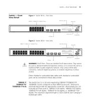
... 1 2 3 4 5 6 7 8 9 10 11 12 9 10 11 12 Module Active Self Test LED Console Port Port Status LEDs Power LED 1 13 67 18 19 3C17400 Switch 3824 Port Status 12 1 2 3 4 5 6 7 8 9 10 11 12 Link/Activity: Green = 1000M, Yellow = 10/100M, Flash = Activity 21 22 23 24... front view 10BASE-T / 100BASE-TX / 1000BASE-T Ports Port Status LEDs Power LED 1 6 9 10 11 7 12 SFP Ports Figure 2 Switch 3824- Only connect RJ-45 data connectors, network telephony systems, or network telephones to these ports to a traditional PBX or public telephone network. ...
... 1 2 3 4 5 6 7 8 9 10 11 12 9 10 11 12 Module Active Self Test LED Console Port Port Status LEDs Power LED 1 13 67 18 19 3C17400 Switch 3824 Port Status 12 1 2 3 4 5 6 7 8 9 10 11 12 Link/Activity: Green = 1000M, Yellow = 10/100M, Flash = Activity 21 22 23 24... front view 10BASE-T / 100BASE-TX / 1000BASE-T Ports Port Status LEDs Power LED 1 6 9 10 11 7 12 SFP Ports Figure 2 Switch 3824- Only connect RJ-45 data connectors, network telephony systems, or network telephones to these ports to a traditional PBX or public telephone network. ...

User Manual
Page 16
...flow control modes are combination ports. The last four 10/100/1000 ports are negotiated. LEDs Table 4 lists LEDs visible on the 24-port Switch. SFP Ports The four SFP (Small Form Factor Pluggable) ports support fiber Gigabit Ethernet short-wave (SX) and long-wave (LX) SFP ...Transceivers in any combination. 16 CHAPTER 1: INTRODUCING THE SWITCH 3812 AND SWITCH 3824 The default state for 10/100/1000 Mbps ports is a loop back error. Alternatively, auto-negotiation can be disabled and the speed,...
...flow control modes are combination ports. The last four 10/100/1000 ports are negotiated. LEDs Table 4 lists LEDs visible on the 24-port Switch. SFP Ports The four SFP (Small Form Factor Pluggable) ports support fiber Gigabit Ethernet short-wave (SX) and long-wave (LX) SFP ...Transceivers in any combination. 16 CHAPTER 1: INTRODUCING THE SWITCH 3812 AND SWITCH 3824 The default state for 10/100/1000 Mbps ports is a loop back error. Alternatively, auto-negotiation can be disabled and the speed,...
User Manual
Page 17
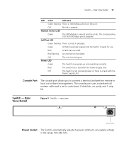
... Green flashing There is a fault with the Power Supply Unit. The console port uses a standard null modem cable and is booting-up and operating normally. Switch - Module Active LEDs Green The SFP Module is present. Console Port The console port allows you to auto-baud, 8 data bits, no parity and 1 ... in progress. Rear View Detail 17 LED Color Indicates Green flashing There is ready for use. Green All tests have been passed and the Switch is 1000 Mbps activity on the port. Off The unit is set to connect a terminal and perform remote or local out-of-band management...
... Green flashing There is a fault with the Power Supply Unit. The console port uses a standard null modem cable and is booting-up and operating normally. Switch - Module Active LEDs Green The SFP Module is present. Console Port The console port allows you to auto-baud, 8 data bits, no parity and 1 ... in progress. Rear View Detail 17 LED Color Indicates Green flashing There is ready for use. Green All tests have been passed and the Switch is 1000 Mbps activity on the port. Off The unit is set to connect a terminal and perform remote or local out-of-band management...
User Manual
Page 18
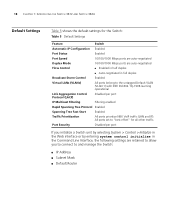
... Start Enabled Traffic Prioritization All ports prioritize NBX VoIP traffic (LAN and IP). Port Security Disabled per port If you initialize a Switch unit by selecting System > Control > Initialize in the Web interface or by entering system control initialize in the Command Line Interface,... in full duplex Broadcast Storm Control Enabled Virtual LANs (VLANs) All ports belong to "best effort" for the Switch: Table 5 Default Settings Feature Switch Automatic IP Configuration Enabled Port Status Enabled Port Speed 10/100/1000 Mbps ports are auto-negotiated Duplex Mode 10/...
... Start Enabled Traffic Prioritization All ports prioritize NBX VoIP traffic (LAN and IP). Port Security Disabled per port If you initialize a Switch unit by selecting System > Control > Initialize in the Web interface or by entering system control initialize in the Command Line Interface,... in full duplex Broadcast Storm Control Enabled Virtual LANs (VLANs) All ports belong to "best effort" for the Switch: Table 5 Default Settings Feature Switch Automatic IP Configuration Enabled Port Status Enabled Port Speed 10/100/1000 Mbps ports are auto-negotiated Duplex Mode 10/...

User Manual
Page 19
...les informations relatives à la sécurité qui se trouvent dans l'Appendice A de ce guide. 2 INSTALLING THE SWITCH This chapter contains the information you must read the safety information provided in diesem Handbuch aufgefuehrt sind. It covers the following topics... Choosing a Suitable Site ■ Rack-mounting ■ Placing Units On Top of this guide. Bevor Sie Komponenten aus dem Switch entfernen oder dem Switch hinzufuegen oder Instandhaltungsarbeiten verrichten, lesen Sie die Sicherheitsanweisungen, die in Appendix A (Anhang A) in Appendix A of Each Other ■...
...les informations relatives à la sécurité qui se trouvent dans l'Appendice A de ce guide. 2 INSTALLING THE SWITCH This chapter contains the information you must read the safety information provided in diesem Handbuch aufgefuehrt sind. It covers the following topics... Choosing a Suitable Site ■ Rack-mounting ■ Placing Units On Top of this guide. Bevor Sie Komponenten aus dem Switch entfernen oder dem Switch hinzufuegen oder Instandhaltungsarbeiten verrichten, lesen Sie die Sicherheitsanweisungen, die in Appendix A (Anhang A) in Appendix A of Each Other ■...

User Manual
Page 20
...sources of electrical noise such as radios, transmitters and broadband amplifiers. ■ power lines and fluorescent lighting fixtures ■ The Switch is accessible and cables can be greater than room ambient temperature. A rack-mounting kit containing two mounting brackets is suited for ... aggregator for other Hubs and Switches. If the Switch is not restricted around the Switch does not exceed 40 °C (104 °F). Alternatively, the Switch can be connected easily. ■ Water or moisture cannot enter the case of the Switch. 3Com recommends that the ventilation holes are...
...sources of electrical noise such as radios, transmitters and broadband amplifiers. ■ power lines and fluorescent lighting fixtures ■ The Switch is accessible and cables can be greater than room ambient temperature. A rack-mounting kit containing two mounting brackets is suited for ... aggregator for other Hubs and Switches. If the Switch is not restricted around the Switch does not exceed 40 °C (104 °F). Alternatively, the Switch can be connected easily. ■ Water or moisture cannot enter the case of the Switch. 3Com recommends that the ventilation holes are...

User Manual
Page 21
... surface, with the front facing towards you. 2 Locate a mounting bracket over the mounting holes on one another, if the units are free-standing. ■ The Switch is situated away from sources of conductive (electrical) dust, for example laser printers. ■ The AC supply used by the... Switch is separate to that used by units that generate high levels of AC noise, for example air conditioning units and laser printers. Rack-mounting 21 &#...
... surface, with the front facing towards you. 2 Locate a mounting bracket over the mounting holes on one another, if the units are free-standing. ■ The Switch is situated away from sources of conductive (electrical) dust, for example laser printers. ■ The AC supply used by the... Switch is separate to that used by units that generate high levels of AC noise, for example air conditioning units and laser printers. Rack-mounting 21 &#...

User Manual
Page 22
... Damage caused to the unit by using incorrect screws invalidates your warranty. 4 Repeat steps 2 and 3 for the other side of the Switch You may need this information for rack-mounting 3 Insert the two screws and tighten with the mounting brackets. Ensure that ventilation holes are not...The unit information label shows the following: ■ The 3Com product name of the Switch ■ The 3Com 3C number of the Switch ■ The unique MAC address (Ethernet address) of the Switch ■ The serial number of the Switch. 5 Insert the Switch into the 19-inch rack and secure with suitable screws...
... Damage caused to the unit by using incorrect screws invalidates your warranty. 4 Repeat steps 2 and 3 for the other side of the Switch You may need this information for rack-mounting 3 Insert the two screws and tighten with the mounting brackets. Ensure that ventilation holes are not...The unit information label shows the following: ■ The 3Com product name of the Switch ■ The 3Com 3C number of the Switch ■ The unique MAC address (Ethernet address) of the Switch ■ The serial number of the Switch. 5 Insert the Switch into the 19-inch rack and secure with suitable screws...

User Manual
Page 23
...up with the recesses of the lower unit. If you are mixing a variety of 3Com Switch and Hub units, the smaller units must use the self-adhesive rubber pads supplied. Apply the pads to...POST), which takes approximately 60 seconds. Powering-up the Use the following sections describe how to get your Switch powered-up and ready for Correct Operation of LEDs During the Power On Self Test, all ports on ... will go off for the LED. If you must be placed one on the Switch are disabled. The Switch is operating correctly. Placing Units On Top of Each Other 23 Placing Units On Top of ...
...up with the recesses of the lower unit. If you are mixing a variety of 3Com Switch and Hub units, the smaller units must use the self-adhesive rubber pads supplied. Apply the pads to...POST), which takes approximately 60 seconds. Powering-up the Use the following sections describe how to get your Switch powered-up and ready for Correct Operation of LEDs During the Power On Self Test, all ports on ... will go off for the LED. If you must be placed one on the Switch are disabled. The Switch is operating correctly. Placing Units On Top of Each Other 23 Placing Units On Top of ...

User Manual
Page 24
See Table 8. 3Com recommends that is they have a cross-over cable. The port can make a connection to use Category 5 ...cross-over ). the maximum segment length for this type of the 10/100/1000 Mbps ports on the Switch are Auto-MDIX, that you need a cross-over capability. Many ports on page 46. If auto-negotiation is disabled, all the... Switch ports are configured as MDIX (cross-over cable (MDIX). If there is evidence of connecting or disconnecting mains...
See Table 8. 3Com recommends that is they have a cross-over cable. The port can make a connection to use Category 5 ...cross-over ). the maximum segment length for this type of the 10/100/1000 Mbps ports on the Switch are Auto-MDIX, that you need a cross-over capability. Many ports on page 46. If auto-negotiation is disabled, all the... Switch ports are configured as MDIX (cross-over cable (MDIX). If there is evidence of connecting or disconnecting mains...