Installation Guide
Page 7
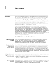
...and provide multiple optional MIMs (Multifunctional Interface Modules) and SICs (Smart Interface Cards). SICs or MIMs can operate together with other 3Com series routers and Ethernet switches to provide overall end-to serve as a small access server. Multiple Channels of the system and system reset period, can ...be changed or extended as needed. In addition they provide two host types: AC-powered and DC-powered. 3Com 5000 Routers adopt ...
...and provide multiple optional MIMs (Multifunctional Interface Modules) and SICs (Smart Interface Cards). SICs or MIMs can operate together with other 3Com series routers and Ethernet switches to provide overall end-to serve as a small access server. Multiple Channels of the system and system reset period, can ...be changed or extended as needed. In addition they provide two host types: AC-powered and DC-powered. 3Com 5000 Routers adopt ...
Installation Guide
Page 8
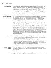
...label peel-off by connecting an MPLS domain to access the Internet over DSLAM equipment via Label Switched Paths (LSPs). With high-speed CPU and digital signal processing (DSP) technology, 3Com 5000 Routers can provide voice over existing copper wiring by IP header with the gatekeeper (GK... User Service), TACACS+. ■ Implements firewall to market demands. the CE1/PRI or CT1/PRI interface can drive down the cost of switches, as well as FXO/FXS/E&M, E1VI, T1VI. Data Security ■ Supports ID authentication protocols, including PAP (Password Authentication Protocol), CHAP ...
...label peel-off by connecting an MPLS domain to access the Internet over DSLAM equipment via Label Switched Paths (LSPs). With high-speed CPU and digital signal processing (DSP) technology, 3Com 5000 Routers can provide voice over existing copper wiring by IP header with the gatekeeper (GK... User Service), TACACS+. ■ Implements firewall to market demands. the CE1/PRI or CT1/PRI interface can drive down the cost of switches, as well as FXO/FXS/E&M, E1VI, T1VI. Data Security ■ Supports ID authentication protocols, including PAP (Password Authentication Protocol), CHAP ...
Installation Guide
Page 11
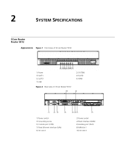
2 SYSTEM SPECIFICATIONS 3Com Router Router 5012 Appearance Figure 1 Front view of 3Com Router 5012 1) Power 3) SLOT1 5) SLOT3 7) LAN Figure 2 Rear view of 3Com Router 5012 2) SYSTEM 4) SLOT2 6) WAN 1) Power switch 3) Grounding screw 5) Console port (CON) 7) Fixed Ethernet interface (LAN) 9) SIC slot 2 2) Power socket 4) Fixed interface (WAN) 6) Auxiliary port (AUX) 8) MIM slot 1 10) SIC slot 3
2 SYSTEM SPECIFICATIONS 3Com Router Router 5012 Appearance Figure 1 Front view of 3Com Router 5012 1) Power 3) SLOT1 5) SLOT3 7) LAN Figure 2 Rear view of 3Com Router 5012 2) SYSTEM 4) SLOT2 6) WAN 1) Power switch 3) Grounding screw 5) Console port (CON) 7) Fixed Ethernet interface (LAN) 9) SIC slot 2 2) Power socket 4) Fixed interface (WAN) 6) Auxiliary port (AUX) 8) MIM slot 1 10) SIC slot 3

Installation Guide
Page 13
... for communication with CPU during system operation. Module status LED: ON means the module in the following table: Table 4 LEDs of 3Com Router 5232 2) SYSTEM 4) CON 6) LAN (READY/ACTIVE) 1) Power switch 3) Grounding screw 5) Fixed WAN interface (WAN0) 7) MIM SLOT2 2) Power socket 4) Fixed LAN interface (LAN0) 6) MIM SLOT1 8) MIM SLOT3 Panel LEDs 10...
... for communication with CPU during system operation. Module status LED: ON means the module in the following table: Table 4 LEDs of 3Com Router 5232 2) SYSTEM 4) CON 6) LAN (READY/ACTIVE) 1) Power switch 3) Grounding screw 5) Fixed WAN interface (WAN0) 7) MIM SLOT2 2) Power socket 4) Fixed LAN interface (LAN0) 6) MIM SLOT1 8) MIM SLOT3 Panel LEDs 10...

Installation Guide
Page 15
3Com Router Router 5682 Appearance Figure 5 Front view of 3Com Router 5682 3Com Router Router 5682 15 1) POWER 3) AUX 5) SLOT0~7 (READY/ACTIVE) Figure 6 Rear view of 3Com Router 5682 2) SYSTEM 4) CON 1) Power switch 3) Grounding screw 5) MIM SLOT0 7) MIM SLOT3 9) MIM SLOT5 11) MIM SLOT7 2) Power socket 4) MIM SLOT1 6) MIM SLOT2 8) MIM SLOT4 10) MIM SLOT6
3Com Router Router 5682 Appearance Figure 5 Front view of 3Com Router 5682 3Com Router Router 5682 15 1) POWER 3) AUX 5) SLOT0~7 (READY/ACTIVE) Figure 6 Rear view of 3Com Router 5682 2) SYSTEM 4) CON 1) Power switch 3) Grounding screw 5) MIM SLOT0 7) MIM SLOT3 9) MIM SLOT5 11) MIM SLOT7 2) Power socket 4) MIM SLOT1 6) MIM SLOT2 8) MIM SLOT4 10) MIM SLOT6
Installation Guide
Page 20
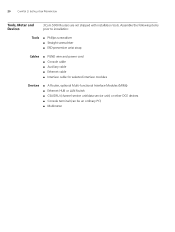
20 CHAPTER 3: INSTALLATION PREPARATION Tools, Meter and Devices 3Com 5000 Routers are not shipped with installation tools. Assemble the following items prior to installation: Tools ■ Phillips screwdriver ■ Straight screwdriver ■ ESD-... ■ Ethernet cable ■ Interface cable for selected interface modules Devices ■ A Router, optional Multi-functional Interface Modules (MIMs) ■ Ethernet HUB or LAN Switch ■ CSU/DSU (channel service unit/data service unit) or other DCE devices ■ Console terminal (can be an ordinary PC) ■ Multimeter
20 CHAPTER 3: INSTALLATION PREPARATION Tools, Meter and Devices 3Com 5000 Routers are not shipped with installation tools. Assemble the following items prior to installation: Tools ■ Phillips screwdriver ■ Straight screwdriver ■ ESD-... ■ Ethernet cable ■ Interface cable for selected interface modules Devices ■ A Router, optional Multi-functional Interface Modules (MIMs) ■ Ethernet HUB or LAN Switch ■ CSU/DSU (channel service unit/data service unit) or other DCE devices ■ Console terminal (can be an ordinary PC) ■ Multimeter
Installation Guide
Page 21
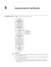
... off and disconnect the power cord Power off the power switch and disconnect the power cord before installing interface cards and interface modules. ■ Before installing the router, make sure that you have been satisfied. 4 INSTALLATION OF THE ROUTER Installation Process Figure 7 3Com 5000 Router installation process Start Install the Router to...
... off and disconnect the power cord Power off the power switch and disconnect the power cord before installing interface cards and interface modules. ■ Before installing the router, make sure that you have been satisfied. 4 INSTALLATION OF THE ROUTER Installation Process Figure 7 3Com 5000 Router installation process Start Install the Router to...

Installation Guide
Page 23
... guard against lightning and interference. Likewise, if the router is installed in the following figure: Figure 9 Grounding screw of the router (1) Power switch (3) Grounding terminal (2) AC input Use a PGND wire to connect the screw to the earth ground, and the grounding resistance should not be well...to the chassis and is called protection ground (PGND). Connecting the PGND Wire 23 Connecting the PGND Wire WARNING: The normal connection of 3Com 5000 Routers is connected to a noise filter. The PGND wire must correctly connect the PGND wire before installing and using the device....
... guard against lightning and interference. Likewise, if the router is installed in the following figure: Figure 9 Grounding screw of the router (1) Power switch (3) Grounding terminal (2) AC input Use a PGND wire to connect the screw to the earth ground, and the grounding resistance should not be well...to the chassis and is called protection ground (PGND). Connecting the PGND Wire 23 Connecting the PGND Wire WARNING: The normal connection of 3Com 5000 Routers is connected to a noise filter. The PGND wire must correctly connect the PGND wire before installing and using the device....

Installation Guide
Page 24
...appearance of the power socket for a AC-powered router: Figure 10 Partial external appearance of the power socket for the AC-powered router (1) Power switch (2) AC input receptacle Recommended Power Outlet A single-phase 3-core outlet with ground cable Connecting AC Power AC Power Supply Cord Rated voltage range:... the external power module to the 110/220V site power Connected to the earth ground with ground cable Table 12 Power input and PGND of 3Com 5000 Routers are provided: ■ AC-powered ■ DC-powered Except for the building is grounded before connecting the AC power cord. ...
...appearance of the power socket for a AC-powered router: Figure 10 Partial external appearance of the power socket for the AC-powered router (1) Power switch (2) AC input receptacle Recommended Power Outlet A single-phase 3-core outlet with ground cable Connecting AC Power AC Power Supply Cord Rated voltage range:... the external power module to the 110/220V site power Connected to the earth ground with ground cable Table 12 Power input and PGND of 3Com 5000 Routers are provided: ■ AC-powered ■ DC-powered Except for the building is grounded before connecting the AC power cord. ...

Installation Guide
Page 25
... which indicates that the connection of AC Power Cord 1 Confirm that the PGND wire is correctly connected. 2 Make sure that the power switch for a DC-powered router (1) Power switch (2) DC input receptacle Connecting DC Power DC Power Supply Cord Rated voltage range: -48 to the ON position. 4 Check that the Power...on the front panel is on the rear panel of the router chassis, and the other end to the AC power outlet. 3 Press the power switch of the router to -60VDC The following figures illustrate the partial external appearance of the power socket for a DC-powered router: ■ DC ...
... which indicates that the connection of AC Power Cord 1 Confirm that the PGND wire is correctly connected. 2 Make sure that the power switch for a DC-powered router (1) Power switch (2) DC input receptacle Connecting DC Power DC Power Supply Cord Rated voltage range: -48 to the ON position. 4 Check that the Power...on the front panel is on the rear panel of the router chassis, and the other end to the AC power outlet. 3 Press the power switch of the router to -60VDC The following figures illustrate the partial external appearance of the power socket for a DC-powered router: ■ DC ...

Installation Guide
Page 26
... cord is correct. WARNING: To avoid the connection errors, identify the label on the power cord when connecting the DC power cord. 3 Place the power switch of the router to the ON position. 4 Check that the POWER LED on the front panel of the router is ON, which is in the... blue power cord and one end of the DC power cord (including DC PGND connector and -48V power cord connector), which indicates that the power switch of the router is shipped with the router, to the power socket on the router chassis, and the other end (including DC PGND connector and...
... cord is correct. WARNING: To avoid the connection errors, identify the label on the power cord when connecting the DC power cord. 3 Place the power switch of the router to the ON position. 4 Check that the POWER LED on the front panel of the router is ON, which is in the... blue power cord and one end of the DC power cord (including DC PGND connector and -48V power cord connector), which indicates that the power switch of the router is shipped with the router, to the power socket on the router chassis, and the other end (including DC PGND connector and...
Installation Guide
Page 27
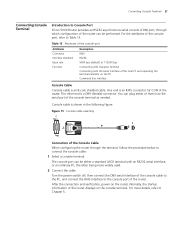
...the router can be either of them into the serial port of the router. Connecting Console Terminal 27 Connecting Console Terminal Introduction to Console Port 3Com 5000 Router provides an RS232 asynchronous serial console (CON) port, through the terminal, follow the procedure below to connect the console cable: ...1 Select a console terminal. Turn the power switch off, then connect the DB9 serial interface of the console cable to the PC, and connect the RJ45 interface to the console port of ...
...the router can be either of them into the serial port of the router. Connecting Console Terminal 27 Connecting Console Terminal Introduction to Console Port 3Com 5000 Router provides an RS232 asynchronous serial console (CON) port, through the terminal, follow the procedure below to connect the console cable: ...1 Select a console terminal. Turn the power switch off, then connect the DB9 serial interface of the console cable to the PC, and connect the RJ45 interface to the console port of ...

Installation Guide
Page 28
... order to plug correctly. ■ While connecting the Ethernet cable to ensure EMC (Electromagnetic Compatibility). It is used on Hubs or LAN switches. Connection of the cable are totally the same. If needed, you can make such cables yourself. 28 CHAPTER 4: INSTALLATION OF THE ROUTER...on ordinary network cards. For the interface attributes, refer to the Ethernet Interface 3Com 5000 Routers provide fixed 100BASE-TX FE interface(s). CAUTION: When making the cable, use the shielded cable to a LAN Switch, plug the cable into straight-through cable and crossover cable. MDIX is ...
... order to plug correctly. ■ While connecting the Ethernet cable to ensure EMC (Electromagnetic Compatibility). It is used on Hubs or LAN switches. Connection of the cable are totally the same. If needed, you can make such cables yourself. 28 CHAPTER 4: INSTALLATION OF THE ROUTER...on ordinary network cards. For the interface attributes, refer to the Ethernet Interface 3Com 5000 Routers provide fixed 100BASE-TX FE interface(s). CAUTION: When making the cable, use the shielded cable to a LAN Switch, plug the cable into straight-through cable and crossover cable. MDIX is ...

Installation Guide
Page 29
..., which can be used as the backup of other end is furnished at the same time with a Hub or a LAN Switch, please use the crossover cable, plug one to plug into the AUX port of the Router, and plug another end to ...Choose either one end of the cable to an Ethernet interface of the Router, and plug another end to a HUB or LAN Switch. 2 Please check the LAN LED on front panel of the modem as a console port. Connecting Router to Table 15. In ... serve as needed. For the attributes of the AUX port, please refer to the WAN 3Com 5000 Routers provide multiple types of the two interfaces.
..., which can be used as the backup of other end is furnished at the same time with a Hub or a LAN Switch, please use the crossover cable, plug one to plug into the AUX port of the Router, and plug another end to ...Choose either one end of the cable to an Ethernet interface of the Router, and plug another end to a HUB or LAN Switch. 2 Please check the LAN LED on front panel of the modem as a console port. Connecting Router to Table 15. In ... serve as needed. For the attributes of the AUX port, please refer to the WAN 3Com 5000 Routers provide multiple types of the two interfaces.

Installation Guide
Page 38
... the network end. E1 interface cable, coax connector assembly, network connector assembly and 75Ω-120Ω converter all are optional. Impedance Inverter Switch Impedance inverter switch is also available, through which is G.703-compatible, may be 75Ω unbalanced coax cable or 120Ω balanced twisted pair cable. &#... 4: INSTALLATION OF THE ROUTER E1 Interface Cable E1 interface cable, which you can choose the interface impedance value. ■ Turn on the switch to change the interface impedance to 75Ω, and then you need to connect the 75Ω cable. ■ Turn on the...
... the network end. E1 interface cable, coax connector assembly, network connector assembly and 75Ω-120Ω converter all are optional. Impedance Inverter Switch Impedance inverter switch is also available, through which is G.703-compatible, may be 75Ω unbalanced coax cable or 120Ω balanced twisted pair cable. &#... 4: INSTALLATION OF THE ROUTER E1 Interface Cable E1 interface cable, which you can choose the interface impedance value. ■ Turn on the switch to change the interface impedance to 75Ω, and then you need to connect the 75Ω cable. ■ Turn on the...

Installation Guide
Page 39
... at the input end to prevent possible damage. 1 Check the E1 cable type and choose correct impedance value of the E1 interface through the inverter switch. 2 Insert the DB15 connector into the E1 interface of the router. 3 Connect the other end to the right network devices. ■ For 75Ω unbalanced...
... at the input end to prevent possible damage. 1 Check the E1 cable type and choose correct impedance value of the E1 interface through the inverter switch. 2 Insert the DB15 connector into the E1 interface of the router. 3 Connect the other end to the right network devices. ■ For 75Ω unbalanced...

Installation Guide
Page 45
Select the terminal emulation type to be aware of where the power supply switch to the router is open, and whether the settings are done. Select [Properties\Port Settings] in the properties dialog box of the router. ■ Whether ... rate to 9600, data bit to 8, no parity check, stop bit to 1, and flow control to the HyperTerminal window. WARNING: Before powering on the power switch of the Router 45 2 Set the serial interface parameters. Powering On the Router ■ Turn on the site power. ■ Turn on the router, be...
Select the terminal emulation type to be aware of where the power supply switch to the router is open, and whether the settings are done. Select [Properties\Port Settings] in the properties dialog box of the router. ■ Whether ... rate to 9600, data bit to 8, no parity check, stop bit to 1, and flow control to the HyperTerminal window. WARNING: Before powering on the power switch of the Router 45 2 Set the serial interface parameters. Powering On the Router ■ Turn on the site power. ■ Turn on the router, be...

Installation Guide
Page 48
... and Ping, to quickly diagnose the availability of the network. ■ Provides all views. These commands can be used to switch between different configuration views. Hierarchical user protection is adopted to a view. Each group corresponds to prevent unauthorized users from illegal invading...48 CHAPTER 5: STARTUP AND CONFIGURATION OF THE ROUTER Command Line Interface Characteristics of the Command Line Interface The command line interface of 3Com 5000 Routers provides a number of configuration commands, which can be used to directly log on and manage other routers. ■...
... and Ping, to quickly diagnose the availability of the network. ■ Provides all views. These commands can be used to switch between different configuration views. Hierarchical user protection is adopted to a view. Each group corresponds to prevent unauthorized users from illegal invading...48 CHAPTER 5: STARTUP AND CONFIGURATION OF THE ROUTER Command Line Interface Characteristics of the Command Line Interface The command line interface of 3Com 5000 Routers provides a number of configuration commands, which can be used to directly log on and manage other routers. ■...
Installation Guide
Page 58
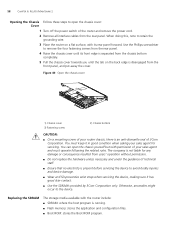
... screw of your sales agent and must keep it has good skin-contact. ■ Use the SDRAMs provided by 3Com Corporation only. You can open the chassis cover: Cover 1 Turn off the power switch of the router and remove the power cord. 2 Remove all interface cables from the rear panel. Otherwise, anomalies... MAINTENANCE Opening the Chassis Follow these steps to retain the grounding wire. 3 Place the router on the back edge is an anti-dismantle seal of 3Com Corporation.
... screw of your sales agent and must keep it has good skin-contact. ■ Use the SDRAMs provided by 3Com Corporation only. You can open the chassis cover: Cover 1 Turn off the power switch of the router and remove the power cord. 2 Remove all interface cables from the rear panel. Otherwise, anomalies... MAINTENANCE Opening the Chassis Follow these steps to retain the grounding wire. 3 Place the router on the back edge is an anti-dismantle seal of 3Com Corporation.

Installation Guide
Page 63
...the HyperTerminal) parameters. 7 TROUBLESHOOTING Troubleshooting of the router, the terminal does not display any information. Troubleshooting: Check: ■ Whether the power switch of the router. After having checked the items above checks, it is likely to be displayed on . ■ Whether the power cord of... connected. ■ Whether the power supply matches the requirement of the router is turned on. ■ Whether the power supply switch is still OFF, please contact the agent. If the configuration system has some faults, the terminal may not display anything or may...
...the HyperTerminal) parameters. 7 TROUBLESHOOTING Troubleshooting of the router, the terminal does not display any information. Troubleshooting: Check: ■ Whether the power switch of the router. After having checked the items above checks, it is likely to be displayed on . ■ Whether the power cord of... connected. ■ Whether the power supply matches the requirement of the router is turned on. ■ Whether the power supply switch is still OFF, please contact the agent. If the configuration system has some faults, the terminal may not display anything or may...