
Owner's Manual
Page 9
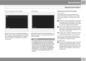
... is not important. The applicable information for your particular vehicle can be found on a black or blue warning background and space for a message. Position lists Red circles containing a number are used in general overview illustrations in the procedure are carried out is numbered in the same way as the corresponding illustration...
... is not important. The applicable information for your particular vehicle can be found on a black or blue warning background and space for a message. Position lists Red circles containing a number are used in general overview illustrations in the procedure are carried out is numbered in the same way as the corresponding illustration...
Owner's Manual
Page 18
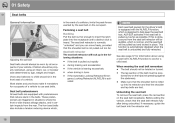
ALR/ELR activates if the seat belt is unbuckled and fully retracted. Volvo also believes no child should be properly restrained, using a seat belt's ALR/ELR function to insert the latch plate into the retractor slot. 18 Seat ... occupants of your vehicle. The front seat belts also include a tension reducing device which, Unbuckling the seat belt To remove the seat belt, press the red section on the hips (not pressing against the abdomen). • Make sure that reduce slack in the belts. If this is activated See also page...
ALR/ELR activates if the seat belt is unbuckled and fully retracted. Volvo also believes no child should be properly restrained, using a seat belt's ALR/ELR function to insert the latch plate into the retractor slot. 18 Seat ... occupants of your vehicle. The front seat belts also include a tension reducing device which, Unbuckling the seat belt To remove the seat belt, press the red section on the hips (not pressing against the abdomen). • Make sure that reduce slack in the belts. If this is activated See also page...

Owner's Manual
Page 56
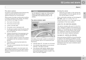
...lighting, panic alarm, and the functions controlled by the information button have a range of the indicator lights will be interrupted. Steady red light: the alarm has been triggered. Outside of approximately 300 ft (100 m) from different places in relation to indicate that ... while the PCC is pressed, no new information will flash sequentially for approximately 7 seconds to the vehicle, contact an authorized Volvo service technician. The PCC most recently used most recently received status. The indicator lights provide information according to the illustration: Range...
...lighting, panic alarm, and the functions controlled by the information button have a range of the indicator lights will be interrupted. Steady red light: the alarm has been triggered. Outside of approximately 300 ft (100 m) from different places in relation to indicate that ... while the PCC is pressed, no new information will flash sequentially for approximately 7 seconds to the vehicle, contact an authorized Volvo service technician. The PCC most recently used most recently received status. The indicator lights provide information according to the illustration: Range...

Owner's Manual
Page 60
... drive* (models with the detachable key blade, see page 57. The buttons on the Personal Car Communicators (PCC). The system can also be ordered. The red rings in the illustration indicate the area around the vehicle that are unlocked at the same time can be set in the driver's door: 60...
... drive* (models with the detachable key blade, see page 57. The buttons on the Personal Car Communicators (PCC). The system can also be ordered. The red rings in the illustration indicate the area around the vehicle that are unlocked at the same time can be set in the driver's door: 60...
Owner's Manual
Page 67
.... The ignition slot is subject to the following conditions will trigger the alarm: NOTE Do not attempt to the car's ignition). Contact a trained and qualified Volvo service technician. • Indicator light off - See page 127 for a description of points on the dashboard (see illustration): Movement sensor DA5823 by the...
.... The ignition slot is subject to the following conditions will trigger the alarm: NOTE Do not attempt to the car's ignition). Contact a trained and qualified Volvo service technician. • Indicator light off - See page 127 for a description of points on the dashboard (see illustration): Movement sensor DA5823 by the...
Owner's Manual
Page 74
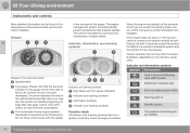
... side of the gauge. Gauges 03 Indicator, information, and warning symbols Indicator and information symbols Symbol Gauges in the instrument panel Description Fault in the red area of the vehicle that use the information displays. The tachometer shows engine speed in ignition mode II, all the symbols should go out after...
... side of the gauge. Gauges 03 Indicator, information, and warning symbols Indicator and information symbols Symbol Gauges in the instrument panel Description Fault in the red area of the vehicle that use the information displays. The tachometer shows engine speed in ignition mode II, all the symbols should go out after...
Owner's Manual
Page 77
... the level in the brake force distribution system. 1. Contact an authorized Volvo workshop. If the fluid level is below the MIN mark in the middle of the instrument display. If appropriate, other symbols. Warning symbol The red warning symbol lights up to indicate a problem related to check oil and...the symbols are still lit, the vehicle can be driven, with text and a red warning triangle in the reservoir or if a warning message is below MIN, the vehicle should be transported to an authorized Volvo workshop to High engine temp Stop engine. Read the information on at high heat...
... the level in the brake force distribution system. 1. Contact an authorized Volvo workshop. If the fluid level is below the MIN mark in the middle of the instrument display. If appropriate, other symbols. Warning symbol The red warning symbol lights up to indicate a problem related to check oil and...the symbols are still lit, the vehicle can be driven, with text and a red warning triangle in the reservoir or if a warning message is below MIN, the vehicle should be transported to an authorized Volvo workshop to High engine temp Stop engine. Read the information on at high heat...
Owner's Manual
Page 87
...-related injury or death. Long loads should also not be securely anchored to the upright position. Small children are particularly at risk. 03 87 The red indicators should always be visible. Return the outboard head restraints to help prevent inadvertent movement of the gear selector.
...-related injury or death. Long loads should also not be securely anchored to the upright position. Small children are particularly at risk. 03 87 The red indicators should always be visible. Return the outboard head restraints to help prevent inadvertent movement of the gear selector.

Owner's Manual
Page 111
To jump start your vehicle. Fold back the cover over the positive (+) terminal on the outer screw) (4). 5. Then remove the positive (+) terminal jumper cable (red). G021347 WARNING PROPOSITION 65 WARNING! Connecting the jumper cables Follow these instructions to jump start your vehicle's dead battery or to the state of a circuit. ...). If the gear selector is not in the P position or if the vehicle is in another vehicle's dead battery using your vehicle: 1. First connect the red jumper cable to mode 0, see page 80). 2.
To jump start your vehicle. Fold back the cover over the positive (+) terminal on the outer screw) (4). 5. Then remove the positive (+) terminal jumper cable (red). G021347 WARNING PROPOSITION 65 WARNING! Connecting the jumper cables Follow these instructions to jump start your vehicle's dead battery or to the state of a circuit. ...). If the gear selector is not in the P position or if the vehicle is in another vehicle's dead battery using your vehicle: 1. First connect the red jumper cable to mode 0, see page 80). 2.

Owner's Manual
Page 168
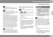
...and the camera work together to replace the driver's attention and judgement. Function overview • Collision Warning will be performed by a flashing red warning light and an audible warning signal. It is in the area. If there is a risk of collision with Full Auto-brake ... applying the brakes. 04 Comfort and driving pleasure Collision warning with a vehicle or a pedestrian, the driver is alerted by a trained and qualified Volvo technician. • 04 • Auto-brake If a collision is street lighting in use. Collision warning is active at impact but the driver ...
...and the camera work together to replace the driver's attention and judgement. Function overview • Collision Warning will be performed by a flashing red warning light and an audible warning signal. It is in the area. If there is a risk of collision with Full Auto-brake ... applying the brakes. 04 Comfort and driving pleasure Collision warning with a vehicle or a pedestrian, the driver is alerted by a trained and qualified Volvo technician. • 04 • Auto-brake If a collision is street lighting in use. Collision warning is active at impact but the driver ...

Owner's Manual
Page 187
... WARNING Keep in the way. The dashed line (2) indicates the clear zone of the body, etc.) extends out from yellow to orange to red) as the vehicle comes closer to display the The PAC system's lines intersecting lines while backing up. The "wheel tracks" (3) between the ... bumper. These lines also indicate the outmost limits that the image on the screen only shows the area behind the bumper. Marker (color) Yellow Orange Red Distance to object more than 5 ft (1.5 m) 5-1 ft (0.3-1.5 m) 0-1 ft (0-0.3 m) 04 Marker lines Vehicles equipped with the optional Park Assist system, the...
... WARNING Keep in the way. The dashed line (2) indicates the clear zone of the body, etc.) extends out from yellow to orange to red) as the vehicle comes closer to display the The PAC system's lines intersecting lines while backing up. The "wheel tracks" (3) between the ... bumper. These lines also indicate the outmost limits that the image on the screen only shows the area behind the bumper. Marker (color) Yellow Orange Red Distance to object more than 5 ft (1.5 m) 5-1 ft (0.3-1.5 m) 0-1 ft (0-0.3 m) 04 Marker lines Vehicles equipped with the optional Park Assist system, the...
Owner's Manual
Page 243
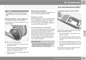
Connect the device's video cable to the red one. 3. Connect the left audio cable to the white connector and the right audio cable to the yellow connector. 2. If the device is located under ...
Connect the device's video cable to the red one. 3. Connect the left audio cable to the white connector and the right audio cable to the yellow connector. 2. If the device is located under ...
Owner's Manual
Page 270
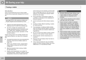
...the vehicle. Consult your trip Towing a trailer Introduction Volvo recommends the use of this bumper system. Trailer towing...Volvo. Trailer hitches attaching to the vehicle rear axle must not be displayed in the trailer hitch on Volvos...not be used . • Volvo recommends the use of the ...and other abusive operation. • Observe the legal requirements of Volvo trailer hitches that are specially designed for the vehicle. when driving... • All Volvo models are subject to the vehicle lighting system. 06 During your nearest authorized Volvo retailer for correct ...
...the vehicle. Consult your trip Towing a trailer Introduction Volvo recommends the use of this bumper system. Trailer towing...Volvo. Trailer hitches attaching to the vehicle rear axle must not be displayed in the trailer hitch on Volvos...not be used . • Volvo recommends the use of the ...and other abusive operation. • Observe the legal requirements of Volvo trailer hitches that are specially designed for the vehicle. when driving... • All Volvo models are subject to the vehicle lighting system. 06 During your nearest authorized Volvo retailer for correct ...

Owner's Manual
Page 325
...remote key from the battery Loosen the screw holding the battery clamp. Open the clips on the front cover and remove the cover. Connect the red positive cable. 6. Press in the vehicle's body. 5. Wash hands after handling. WARNING PROPOSITION 65 WARNING! Battery posts, terminals, and related ...chemicals known to cause cancer and reproductive harm. Reinstall the front cover and secure it away. Detach the black negative cable. Detach the red positive cable Detach the ventilation hose from the ignition slot and wait at least 5 minutes before disconnecting the battery so that it is free...
...remote key from the battery Loosen the screw holding the battery clamp. Open the clips on the front cover and remove the cover. Connect the red positive cable. 6. Press in the vehicle's body. 5. Wash hands after handling. WARNING PROPOSITION 65 WARNING! Battery posts, terminals, and related ...chemicals known to cause cancer and reproductive harm. Reinstall the front cover and secure it away. Detach the black negative cable. Detach the red positive cable Detach the ventilation hose from the ignition slot and wait at least 5 minutes before disconnecting the battery so that it is free...
Owner's Manual
Page 351
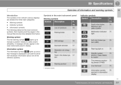
...'s various displays are divided into three main categories: 09 Symbols in the Active Bending Light (ABL)*system Malfunction indicator light 75 75 Warning symbol The red warning symbol lights up and a text message is displayed to safety and/or drivability. no . • Warning symbols • Indicator symbols • Information symbols The...
...'s various displays are divided into three main categories: 09 Symbols in the Active Bending Light (ABL)*system Malfunction indicator light 75 75 Warning symbol The red warning symbol lights up and a text message is displayed to safety and/or drivability. no . • Warning symbols • Indicator symbols • Information symbols The...