

Owners Manual
Page 15
Pictorial index Headlight switch P. 213 Turn signal lever P. 190 Fog light switch P. 226 Instrument panel Glove box P. 449 Power back door main switch ∗ P. 70 Gauges and meters P. 194 Multi-information display P. 202 Horn P. 193 Power (ignition) switch P. 176 Windshield wiper and washer switch P. 229 Rear window wiper and washer switch P. 235 Tilt and telescopic steering control switch P. 105 Hood lock release lever P. 509 Parking brake pedal P. 192 ∗: If equipped 15
Pictorial index Headlight switch P. 213 Turn signal lever P. 190 Fog light switch P. 226 Instrument panel Glove box P. 449 Power back door main switch ∗ P. 70 Gauges and meters P. 194 Multi-information display P. 202 Horn P. 193 Power (ignition) switch P. 176 Windshield wiper and washer switch P. 229 Rear window wiper and washer switch P. 235 Tilt and telescopic steering control switch P. 105 Hood lock release lever P. 509 Parking brake pedal P. 192 ∗: If equipped 15

Owners Manual
Page 21
A Power back door switch ∗ P. 70 B Luggage compartment lights P. 73 Rear seatback lock release levers P. 86 Height selector switch ∗ P. 264 ∗: If equipped 21
A Power back door switch ∗ P. 70 B Luggage compartment lights P. 73 Rear seatback lock release levers P. 86 Height selector switch ∗ P. 264 ∗: If equipped 21
Owners Manual
Page 47
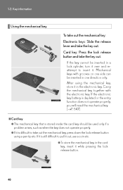
Card key: Press the lock release button and take the key out. After using the mechanical key, store it . If the electronic key battery is depleted or the entry function does ... and reattempt to insert it in one direction only. Key information Using the mechanical key To take out the mechanical key: Electronic keys: Slide the release lever and take the key out. 1-2. If the key cannot be inserted in the electronic key.
Card key: Press the lock release button and take the key out. After using the mechanical key, store it . If the electronic key battery is depleted or the entry function does ... and reattempt to insert it in one direction only. Key information Using the mechanical key To take out the mechanical key: Electronic keys: Slide the release lever and take the key out. 1-2. If the key cannot be inserted in the electronic key.

Owners Manual
Page 94
Lock release button Before driving Up Pull the head restraints up. 1 Down Push the head restraint down while pressing the lock release button. Adjustable components (seats, mirrors, steering wheel) Head restraints Head restraints are provided for all seats. 1-4.
Lock release button Before driving Up Pull the head restraints up. 1 Down Push the head restraint down while pressing the lock release button. Adjustable components (seats, mirrors, steering wheel) Head restraints Head restraints are provided for all seats. 1-4.

Owners Manual
Page 159
1-8. STEP 2 Open the anchor bracket cover, latch the hook onto the anchor bracket and tighten the top tether strap. Safety information Removing a child restraint installed with a top tether strap STEP 1 Secure the child restraint system using a seat belt or the LATCH anchors, and remove the head restraint. Make sure the top tether strap is securely latched. 160 Child restraint systems with a seat belt Press the buckle release button and fully retract the seat belt.
1-8. STEP 2 Open the anchor bracket cover, latch the hook onto the anchor bracket and tighten the top tether strap. Safety information Removing a child restraint installed with a top tether strap STEP 1 Secure the child restraint system using a seat belt or the LATCH anchors, and remove the head restraint. Make sure the top tether strap is securely latched. 160 Child restraint systems with a seat belt Press the buckle release button and fully retract the seat belt.

Owners Manual
Page 188
Lane change to the left hand signals will flash until you release the lever. Driving procedures Turn signal lever The turn signal lever can be used to show the following intention of the driver: Type A Right turn Left turn Lane change to the right (push and hold the lever partway) The left (push and hold the lever partway) The right hand signals will flash until you release the lever. 190 2-1.
Lane change to the left hand signals will flash until you release the lever. Driving procedures Turn signal lever The turn signal lever can be used to show the following intention of the driver: Type A Right turn Left turn Lane change to the right (push and hold the lever partway) The left (push and hold the lever partway) The right hand signals will flash until you release the lever. 190 2-1.

Owners Manual
Page 189
Driving procedures Type B Right turn Left turn Lane change to the right (push and hold the lever partway) The right hand signals will flash until you release the lever. 2 Lane change to the left (push and hold the lever partway) The left hand signals will flash until you release the lever. 2-1. When driving
Driving procedures Type B Right turn Left turn Lane change to the right (push and hold the lever partway) The right hand signals will flash until you release the lever. 2 Lane change to the left (push and hold the lever partway) The left hand signals will flash until you release the lever. 2-1. When driving

Owners Manual
Page 190
Canada Driving procedures Parking brake To set the parking brake, fully depress the parking brake pedal with your left foot while depressing the brake pedal with your right foot. (Depressing the pedal again releases the parking brake.) U.S.A. 2-1.
Canada Driving procedures Parking brake To set the parking brake, fully depress the parking brake pedal with your left foot while depressing the brake pedal with your right foot. (Depressing the pedal again releases the parking brake.) U.S.A. 2-1.

Owners Manual
Page 214
... headlights on, push the lever away from you to the center position to turn them off . AFS operates at intersections and on the high beams. Release the lever to vehicle speed and the degree of the tire angle that are controlled by automatically adjusting the direction of the light axis of...
... headlights on, push the lever away from you to the center position to turn them off . AFS operates at intersections and on the high beams. Release the lever to vehicle speed and the degree of the tire angle that are controlled by automatically adjusting the direction of the light axis of...

Owners Manual
Page 237
The vehicle speed at the moment the lever is released becomes the set the speed. "SET" will be displayed. Using other driving systems STEP 2 Accelerate or decelerate the vehicle to the desired speed, and push the lever down to set speed. 2 When driving 2-4.
The vehicle speed at the moment the lever is released becomes the set the speed. "SET" will be displayed. Using other driving systems STEP 2 Accelerate or decelerate the vehicle to the desired speed, and push the lever down to set speed. 2 When driving 2-4.

Owners Manual
Page 242
"SET" will be displayed. Using other driving systems STEP 2 Accelerate or decelerate the vehicle to the desired speed, and push the lever down to set speed. The vehicle speed at the moment the lever is released becomes the set the speed. 2-4.
"SET" will be displayed. Using other driving systems STEP 2 Accelerate or decelerate the vehicle to the desired speed, and push the lever down to set speed. The vehicle speed at the moment the lever is released becomes the set the speed. 2-4.

Owners Manual
Page 243
Using other driving systems When the set speed is shown in "km/h" Fine adjustment: By approximately 0.6 mph (1 km/h) each time the lever is operated Large adjustment: By approximately 3.1 mph (5 km/h) for each 0.75 seconds the lever is held In the constant speed control mode (→P. 249), the set speed will be increased or decreased as follows: Fine adjustment: By approximately 1 mph (1.6 km/h) each time the lever is operated Large adjustment: The set speed can be increased or decreased continually until the lever is released. 2 When driving 2-4.
Using other driving systems When the set speed is shown in "km/h" Fine adjustment: By approximately 0.6 mph (1 km/h) each time the lever is operated Large adjustment: By approximately 3.1 mph (5 km/h) for each 0.75 seconds the lever is held In the constant speed control mode (→P. 249), the set speed will be increased or decreased as follows: Fine adjustment: By approximately 1 mph (1.6 km/h) each time the lever is operated Large adjustment: The set speed can be increased or decreased continually until the lever is released. 2 When driving 2-4.

Owners Manual
Page 282
2-4. Using other driving systems When the system is also a possibility that the seat belts will retract quickly and the brakes will be applied with a force greater than normal. When the seat belt is locked in the retracted position, stop the vehicle in the situations described above, there is activated in a safe place, release the seat belt and refasten it.
2-4. Using other driving systems When the system is also a possibility that the seat belts will retract quickly and the brakes will be applied with a force greater than normal. When the seat belt is locked in the retracted position, stop the vehicle in the situations described above, there is activated in a safe place, release the seat belt and refasten it.

Owners Manual
Page 310
... brake and brake pedal, and slowly pull or back away from the wheel blocks. Apply the parking brake firmly, and put the transmission in place, release the brakes slowly until the blocks absorb the load. Shift into P and turn off the hybrid system. ● When restarting after parking on a slope, but...
... brake and brake pedal, and slowly pull or back away from the wheel blocks. Apply the parking brake firmly, and put the transmission in place, release the brakes slowly until the blocks absorb the load. Shift into P and turn off the hybrid system. ● When restarting after parking on a slope, but...

Owners Manual
Page 445
Opens Locks Unlocks 3 Using the storage features Glove box Glove box The glove box can be opened by pressing the lock release button and locked and unlocked using the mechanical key. 3-6.
Opens Locks Unlocks 3 Using the storage features Glove box Glove box The glove box can be opened by pressing the lock release button and locked and unlocked using the mechanical key. 3-6.

Owners Manual
Page 451
Interior features STEP 2 Pull up the lever to release the lock and lift the armrest. 455 3-6. This box is useful for temporarily storing sunglasses and similar small items. Rear seat (if equipped) STEP 1 3 Pull down the armrest. Using the storage features Auxiliary boxes Auxiliary boxes Overhead Press in the lid.
Interior features STEP 2 Pull up the lever to release the lock and lift the armrest. 455 3-6. This box is useful for temporarily storing sunglasses and similar small items. Rear seat (if equipped) STEP 1 3 Pull down the armrest. Using the storage features Auxiliary boxes Auxiliary boxes Overhead Press in the lid.

Owners Manual
Page 457
Other interior features Multi-display light control (vehicles without a navigation system) The brightness of the display is adjusted to four levels. Press and release the "DISP" switch until the brightness of the multi-display can be adjusted to the desired level. 3 3-7.
Other interior features Multi-display light control (vehicles without a navigation system) The brightness of the display is adjusted to four levels. Press and release the "DISP" switch until the brightness of the multi-display can be adjusted to the desired level. 3 3-7.

Owners Manual
Page 471
...® button. 3-7. Press and hold one of the rolling code type, proceed to program another device for a garage door, check to a rapid flash, you can release both buttons.
...® button. 3-7. Press and hold one of the rolling code type, proceed to program another device for a garage door, check to a rapid flash, you can release both buttons.

Owners Manual
Page 504
4-3. STEP 1 Pull the hood lock release lever. The hood will pop up the hood catch and lift the hood. 4 Maintenance and care CAUTION Do-it-yourself maintenance Hood Release the lock from the inside of the vehicle to open the hood. STEP 2 Pull up slightly.
4-3. STEP 1 Pull the hood lock release lever. The hood will pop up the hood catch and lift the hood. 4 Maintenance and care CAUTION Do-it-yourself maintenance Hood Release the lock from the inside of the vehicle to open the hood. STEP 2 Pull up slightly.

Owners Manual
Page 569
Do-it-yourself maintenance STEP 2 Unplug the connector while depressing the lock release. 4-3.
Do-it-yourself maintenance STEP 2 Unplug the connector while depressing the lock release. 4-3.