
Owner Manual
Page 240
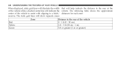
238 UNDERSTANDING THE FEATURES OF YOUR VEHICLE When displayed, static grid lines will illustrate the width that will help indicate the distance to a hitch/ distances for each zone: receiver. The following table shows the approximate center of the vehicle to assist with aligning to the rear of the of the vehicle while a dashed center-line will show separate zones Zone Red Yellow Green Distance to the rear of the vehicle 0 - 1 ft (0 - 30 cm) 1 ft - 3 ft (30 cm - 1 m) 3 ft or greater (1 m or greater) The static grid lines will indicate the vehicle.
238 UNDERSTANDING THE FEATURES OF YOUR VEHICLE When displayed, static grid lines will illustrate the width that will help indicate the distance to a hitch/ distances for each zone: receiver. The following table shows the approximate center of the vehicle to assist with aligning to the rear of the of the vehicle while a dashed center-line will show separate zones Zone Red Yellow Green Distance to the rear of the vehicle 0 - 1 ft (0 - 30 cm) 1 ft - 3 ft (30 cm - 1 m) 3 ft or greater (1 m or greater) The static grid lines will indicate the vehicle.
Owner Manual
Page 618
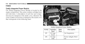
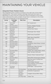
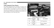
616 MAINTAINING YOUR VEHICLE FUSES Totally Integrated Power Module The Totally Integrated Power Module is stamped on the inside cover that corresponds to the following chart. Totally Integrated Power Module Cavity Cartridge Fuse J01 40 Amp Green J02 30 Amp Pink Mini Fuse Description Air Suspension Power Liftgate Module A description of each fuse and component may be stamped on the inside cover, otherwise the cavity number of each fuse is located in the engine compartment. This center contains cartridge fuses and mini fuses.
616 MAINTAINING YOUR VEHICLE FUSES Totally Integrated Power Module The Totally Integrated Power Module is stamped on the inside cover that corresponds to the following chart. Totally Integrated Power Module Cavity Cartridge Fuse J01 40 Amp Green J02 30 Amp Pink Mini Fuse Description Air Suspension Power Liftgate Module A description of each fuse and component may be stamped on the inside cover, otherwise the cavity number of each fuse is located in the engine compartment. This center contains cartridge fuses and mini fuses.

Owner Manual
Page 621
... Automatic Shutdown 1 and 2 Instrument Cluster Automatic Shutdown 3 Horns (Low/High) - MAINTAINING YOUR VEHICLE 619 Cavity Cartridge Fuse M11 Mini Fuse 10 Amp Red 30 Amp Green 20 Amp Yellow 20 Amp Yellow 20 Amp Yellow Description Heating, Ventilation & Air Conditioning (Climate Control System) Radio/Amplifier Instrument Cluster Cavity Cartridge Fuse M16...
... Automatic Shutdown 1 and 2 Instrument Cluster Automatic Shutdown 3 Horns (Low/High) - MAINTAINING YOUR VEHICLE 619 Cavity Cartridge Fuse M11 Mini Fuse 10 Amp Red 30 Amp Green 20 Amp Yellow 20 Amp Yellow 20 Amp Yellow Description Heating, Ventilation & Air Conditioning (Climate Control System) Radio/Amplifier Instrument Cluster Cavity Cartridge Fuse M16...
User Guide
Page 59
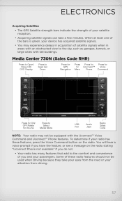
Media Center 730N (Sales Code RHR) NOTE: Your radio may experience delays in acquisition of the bars is green, your passengers. You will hear a voice prompt if you have the feature, or see a message on the radio. Some of these features, press the Voice ...
Media Center 730N (Sales Code RHR) NOTE: Your radio may experience delays in acquisition of the bars is green, your passengers. You will hear a voice prompt if you have the feature, or see a message on the radio. Some of these features, press the Voice ...
User Guide
Page 75
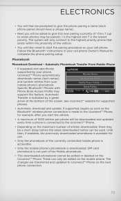
... will then need to start the vehicle. • A maximum of the screen. Automatic Phonebook Transfer From Mobile Phone • If equipped and specifically supported by a green arrow at the bottom of 1000 entries per phone will be downloaded and updated every time a phone is the lowest priority. Until then, if available...
... will then need to start the vehicle. • A maximum of the screen. Automatic Phonebook Transfer From Mobile Phone • If equipped and specifically supported by a green arrow at the bottom of 1000 entries per phone will be downloaded and updated every time a phone is the lowest priority. Until then, if available...
User Guide
Page 97
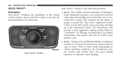
..., hold the shift lever to select the following Selec-Track™ positions: • Sport - The active suspension system will be in Semi Firm mode, and a green flag will light up in the engine controls. 95 Do not downshift for additional stability in or out of the vehicle control systems, along with...
..., hold the shift lever to select the following Selec-Track™ positions: • Sport - The active suspension system will be in Semi Firm mode, and a green flag will light up in the engine controls. 95 Do not downshift for additional stability in or out of the vehicle control systems, along with...
User Guide
Page 130
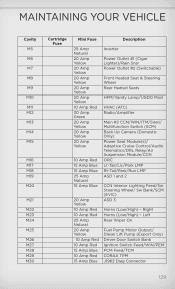
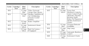
... J01 J02 J03 J04 J05 J06 J07 J08 J09 J10 J11 J13 Cartridge Fuse 40 Amp Green 30 Amp Pink 30 Amp Pink 25 Amp Natural 25 Amp Natural 40 Amp Green 30 Amp Pink 40 Amp Green 30 Amp Pink 30 Amp Pink 30 Amp Pink 60 Amp Yellow 20 Amp Blue... 40 Amp Green 40 Amp Green 20 Amp Blue 60 Amp Yellow 30 Amp Pink 20 Amp Blue 25...
... J01 J02 J03 J04 J05 J06 J07 J08 J09 J10 J11 J13 Cartridge Fuse 40 Amp Green 30 Amp Pink 30 Amp Pink 25 Amp Natural 25 Amp Natural 40 Amp Green 30 Amp Pink 40 Amp Green 30 Amp Pink 30 Amp Pink 30 Amp Pink 60 Amp Yellow 20 Amp Blue... 40 Amp Green 40 Amp Green 20 Amp Blue 60 Amp Yellow 30 Amp Pink 20 Amp Blue 25...
User Guide
Page 131
... Mini Fuse 25 Amp Natural 20 Amp Yellow 20 Amp Yellow 20 Amp Yellow 20 Amp Yellow 20 Amp Yellow 10 Amp Red 30 Amp Green 20 Amp Yellow 20 Amp Yellow 20 Amp Yellow Inverter Power Outlet #1 (Cigar Lighter)/Rain Snsr Power Outlet #2 (Switchable) Front Heated Seat & Steering Wheel Rear...
... Mini Fuse 25 Amp Natural 20 Amp Yellow 20 Amp Yellow 20 Amp Yellow 20 Amp Yellow 20 Amp Yellow 10 Amp Red 30 Amp Green 20 Amp Yellow 20 Amp Yellow 20 Amp Yellow Inverter Power Outlet #1 (Cigar Lighter)/Rain Snsr Power Outlet #2 (Switchable) Front Heated Seat & Steering Wheel Rear...
Owner Manual SRT
Page 236
The static grid lines will indicate the vehicle. The following table shows the approximate center of the vehicle to assist with aligning to the rear of the vehicle while a dashed center-line will show separate zones Zone Red Yellow Green Distance to a hitch/ distances for each zone: receiver. 234 UNDERSTANDING THE FEATURES OF YOUR VEHICLE When displayed, static grid lines will illustrate the width that will help indicate the distance to the rear of the of the vehicle 0 - 1 ft (0 - 30 cm) 1 ft - 3 ft (30 cm - 1 m) 3 ft or greater (1 m or greater)
The static grid lines will indicate the vehicle. The following table shows the approximate center of the vehicle to assist with aligning to the rear of the vehicle while a dashed center-line will show separate zones Zone Red Yellow Green Distance to a hitch/ distances for each zone: receiver. 234 UNDERSTANDING THE FEATURES OF YOUR VEHICLE When displayed, static grid lines will illustrate the width that will help indicate the distance to the rear of the of the vehicle 0 - 1 ft (0 - 30 cm) 1 ft - 3 ft (30 cm - 1 m) 3 ft or greater (1 m or greater)
Owner Manual SRT
Page 428
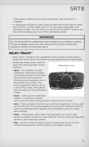
... "AutoStick" in inclement weather. Dry weather, on loose traction surfaces such as snow. The active suspension system will be in Semi Firm mode, and a green flag will light up in Snow mode (depending on an ignition cycle. • Snow - When in the instrument cluster.
... "AutoStick" in inclement weather. Dry weather, on loose traction surfaces such as snow. The active suspension system will be in Semi Firm mode, and a green flag will light up in Snow mode (depending on an ignition cycle. • Snow - When in the instrument cluster.
Owner Manual SRT
Page 429
... and acceleration over two-wheel drive vehicles. Track road calibration for traction. The transmission will go to "AutoStick" in this mode for further information. A green flag will be felt on and off road. Vehicle suspension will be in SPORT mode and provide a more aggressive shifting pattern. Trailer sway control is...
... and acceleration over two-wheel drive vehicles. Track road calibration for traction. The transmission will go to "AutoStick" in this mode for further information. A green flag will be felt on and off road. Vehicle suspension will be in SPORT mode and provide a more aggressive shifting pattern. Trailer sway control is...
Owner Manual SRT
Page 552
550 MAINTAINING YOUR VEHICLE FUSES Totally Integrated Power Module The Totally Integrated Power Module is stamped on the inside cover, otherwise the cavity number of each fuse is located in the engine compartment. Totally Integrated Power Module Cavity Cartridge Fuse J01 40 Amp Green J02 30 Amp Pink Mini Fuse Description Air Suspension Power Liftgate Module This center contains cartridge fuses and mini fuses. A description of each fuse and component may be stamped on the inside cover that corresponds to the following chart.
550 MAINTAINING YOUR VEHICLE FUSES Totally Integrated Power Module The Totally Integrated Power Module is stamped on the inside cover, otherwise the cavity number of each fuse is located in the engine compartment. Totally Integrated Power Module Cavity Cartridge Fuse J01 40 Amp Green J02 30 Amp Pink Mini Fuse Description Air Suspension Power Liftgate Module This center contains cartridge fuses and mini fuses. A description of each fuse and component may be stamped on the inside cover that corresponds to the following chart.
Owner Manual SRT
Page 555
... Telematics/Daytime Running Lights Relay/Air Suspension Module/Instrument Cluster Occupant Restraint Controller Stop Lamp Automatic Shutdown 1 and 2 Instrument Cluster M12 M13 M14 30 Amp Green 20 Amp Yellow 20 Amp Yellow M16 M18 M19 M20 10 Amp Red 15 Amp Blue 25 Amp Natural 15 Amp Blue 7 MAINTAINING YOUR VEHICLE...
... Telematics/Daytime Running Lights Relay/Air Suspension Module/Instrument Cluster Occupant Restraint Controller Stop Lamp Automatic Shutdown 1 and 2 Instrument Cluster M12 M13 M14 30 Amp Green 20 Amp Yellow 20 Amp Yellow M16 M18 M19 M20 10 Amp Red 15 Amp Blue 25 Amp Natural 15 Amp Blue 7 MAINTAINING YOUR VEHICLE...