
Owner Guide 2nd Printing
Page 64
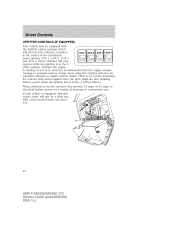
...will only operate while the ignition is in the 4 (ON) position, whether the engine is running to maintain battery charge when using the Upfitter switches for extended duration or higher current draws. (This is even more important for a variety of personal or commercial uses. If your vehicle is ... will also be equipped with a fuse located inside the glove box. 64 2006 F-250/350/450/550 (f23) Owners Guide (post-2002-fmt) USA (fus) These switches will provide four switches, mounted in the 4 [ON] position.) When switched on by the operator they provide 10 amps or 30 amps of the instrument...
...will only operate while the ignition is in the 4 (ON) position, whether the engine is running to maintain battery charge when using the Upfitter switches for extended duration or higher current draws. (This is even more important for a variety of personal or commercial uses. If your vehicle is ... will also be equipped with a fuse located inside the glove box. 64 2006 F-250/350/450/550 (f23) Owners Guide (post-2002-fmt) USA (fus) These switches will provide four switches, mounted in the 4 [ON] position.) When switched on by the operator they provide 10 amps or 30 amps of the instrument...
Owner Guide 2nd Printing
Page 65
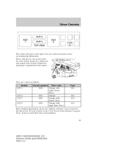
...in the Electrical Wiring section of the Ford Truck Body Builders Layout Book, found as a blunt-cut and sealed wire located behind the passenger compartment fuse panel. Driver Controls The relays and fuse in the glove box are coded as follows: Switch AUX 1 Circuit number Wire color 1936 ...1934 Orange with Yellow Trace 1935 Orange with Light Blue Trace Fuse 30A AUX 2 AUX 3 AUX 4 30A 10A 10A More detailed information about the Upfitter switches can be one power lead for each switch found at www.fleet.ford.com/truckbbas. 65 2006 F-250/350/450/550 (f23) Owners Guide (post-2002-fmt) USA...
...in the Electrical Wiring section of the Ford Truck Body Builders Layout Book, found as a blunt-cut and sealed wire located behind the passenger compartment fuse panel. Driver Controls The relays and fuse in the glove box are coded as follows: Switch AUX 1 Circuit number Wire color 1936 ...1934 Orange with Yellow Trace 1935 Orange with Light Blue Trace Fuse 30A AUX 2 AUX 3 AUX 4 30A 10A 10A More detailed information about the Upfitter switches can be one power lead for each switch found at www.fleet.ford.com/truckbbas. 65 2006 F-250/350/450/550 (f23) Owners Guide (post-2002-fmt) USA...


