
Owner's Manual
Page 56
.... Static can affect radio reception: • Distance/strength. Weak signals are used in stereo. This range can be caused on AM stations by power lines, electric fences, traffic lights and thunderstorms. Moving away from an interfering structure (out of the average FM station is . Hills, mountains and tall buildings between your...
.... Static can affect radio reception: • Distance/strength. Weak signals are used in stereo. This range can be caused on AM stations by power lines, electric fences, traffic lights and thunderstorms. Moving away from an interfering structure (out of the average FM station is . Hills, mountains and tall buildings between your...

Owner's Manual
Page 76
.... 6. Insert the glass end of the new bulb into the lamp assembly until the plastic base contacts the rear of the lamp assembly. 7. Connect the electrical connector into the socket by its plastic base and do not touch the glass. Replacing headlamp bulbs 1. Disconnect the... electrical connector from your dealer. Handle a halogen headlamp bulb carefully and keep out of headlamp assembly. Grasp the bulb only by turning it clockwise until it ...
.... 6. Insert the glass end of the new bulb into the lamp assembly until the plastic base contacts the rear of the lamp assembly. 7. Connect the electrical connector into the socket by its plastic base and do not touch the glass. Replacing headlamp bulbs 1. Disconnect the... electrical connector from your dealer. Handle a halogen headlamp bulb carefully and keep out of headlamp assembly. Grasp the bulb only by turning it clockwise until it ...

Owner's Manual
Page 78
... the new bulb. 4. Lights Replacing foglamp bulbs 1. Carefully pull the bulb straight out of the tail lamp assembly, one just below the other. Disconnect the electrical connector from lamp assembly. 3.
... the new bulb. 4. Lights Replacing foglamp bulbs 1. Carefully pull the bulb straight out of the tail lamp assembly, one just below the other. Disconnect the electrical connector from lamp assembly. 3.
Owner's Manual
Page 84
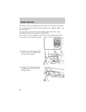
... the instrument panel. There are up to four auxiliary power points in the third row seating position. 84 Use the powerpoint. Do not plug optional electrical accessories into the cigarette lighter. Exceeding this limit may result in a blown fuse. Driver Controls The power point is 20 Amps. The maximum current draw... left side storage compartment in the following locations: • Located on the back side of any single power point is an additional power source for electrical accessories.
... the instrument panel. There are up to four auxiliary power points in the third row seating position. 84 Use the powerpoint. Do not plug optional electrical accessories into the cigarette lighter. Exceeding this limit may result in a blown fuse. Driver Controls The power point is 20 Amps. The maximum current draw... left side storage compartment in the following locations: • Located on the back side of any single power point is an additional power source for electrical accessories.

Owner's Manual
Page 96
... save the displayed zone in memory, release both controls. Compass calibration adjustment Perform this adjustment in the overhead console. 2. For optimum calibration, turn off all electrical accessories (heater/air conditioning, wipers, etc.) and make sure all vehicle doors are in or on the trip computer. 6. Start the vehicle. 96 Magnetic or...
... save the displayed zone in memory, release both controls. Compass calibration adjustment Perform this adjustment in the overhead console. 2. For optimum calibration, turn off all electrical accessories (heater/air conditioning, wipers, etc.) and make sure all vehicle doors are in or on the trip computer. 6. Start the vehicle. 96 Magnetic or...
Owner's Manual
Page 142
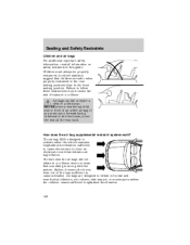
... an active air bag. The fact that the air bags did not inflate in a collision does not mean that children are designed to close an electrical circuit that initiates air bag inflation. Air bags can kill or injure a child in this guide. If you must always be properly restrained. Children must...
... an active air bag. The fact that the air bags did not inflate in a collision does not mean that children are designed to close an electrical circuit that initiates air bag inflation. Air bags can kill or injure a child in this guide. If you must always be properly restrained. Children must...
Owner's Manual
Page 143
...the combustion process that occupants be present which connects the components The diagnostic module monitors its own internal circuits and the supplemental air bag electrical system warning (including the impact sensors), the system wiring, the air bag system readiness light, the air bag back up power ...air bags) • one or more impact and safing sensors • a readiness light and tone • a diagnostic module • and the electrical wiring which may irritate the skin and eyes, but none of cornstarch, talcum powder (to notice a smoke-like, powdery residue or smell the burnt ...
...the combustion process that occupants be present which connects the components The diagnostic module monitors its own internal circuits and the supplemental air bag electrical system warning (including the impact sensors), the system wiring, the air bag system readiness light, the air bag back up power ...air bags) • one or more impact and safing sensors • a readiness light and tone • a diagnostic module • and the electrical wiring which may irritate the skin and eyes, but none of cornstarch, talcum powder (to notice a smoke-like, powdery residue or smell the burnt ...

Owner's Manual
Page 152
... creating the risk of fire or other damage. 152 ON, all Canadian Interference-Causing Equipment standard requirements regulating the impulse electrical field strength of the ignition 1. Extended idling at high engine speeds can be moved from the P (Park) position ...3 operate while the engine is controlled by the powertrain control system. This system meets all electrical circuits operational. Driving STARTING Positions of radio noise. ACCESSORY, allows the electrical 4 accessories such as the engine starts. Only use the accelerator when you have difficulty starting...
... creating the risk of fire or other damage. 152 ON, all Canadian Interference-Causing Equipment standard requirements regulating the impulse electrical field strength of the ignition 1. Extended idling at high engine speeds can be moved from the P (Park) position ...3 operate while the engine is controlled by the powertrain control system. This system meets all electrical circuits operational. Driving STARTING Positions of radio noise. ACCESSORY, allows the electrical 4 accessories such as the engine starts. Only use the accelerator when you have difficulty starting...

Owner's Manual
Page 155
... release the accelerator pedal gradually as the engine speeds up the engine faster and allows the heater-defroster system to START position. 4. To prevent electrical shock, do not use your vehicle immediately. Do not drive if you live in a region where temperatures reach -23°C (-10°F)...brake, shift into gear and drive. Use of any kind inside your vehicle, have your dealer inspect and fix your heater with ungrounded electrical systems or two-pronged (cheater) adapters. Take precautions to floor and hold. These fumes are harmful and could kill you ever smell ...
... release the accelerator pedal gradually as the engine speeds up the engine faster and allows the heater-defroster system to START position. 4. To prevent electrical shock, do not use your vehicle immediately. Do not drive if you live in a region where temperatures reach -23°C (-10°F)...brake, shift into gear and drive. Use of any kind inside your vehicle, have your dealer inspect and fix your heater with ungrounded electrical systems or two-pronged (cheater) adapters. Take precautions to floor and hold. These fumes are harmful and could kill you ever smell ...
Owner's Manual
Page 182
... weight capacity. To connect the trailer's safety chains, cross the chains under the trailer tongue and allow slack for hooking up trailer lamps. Trailer brakes Electric brakes and manual, automatic or surge-type trailer brakes are required on most towed vehicles. The braking system of the tow vehicle is equipped with...
... weight capacity. To connect the trailer's safety chains, cross the chains under the trailer tongue and allow slack for hooking up trailer lamps. Trailer brakes Electric brakes and manual, automatic or surge-type trailer brakes are required on most towed vehicles. The braking system of the tow vehicle is equipped with...
Owner's Manual
Page 183
... not be no more than 10-15% of the loaded trailer weight. • After you have traveled 80 km (50 miles), thoroughly check your hitch, electrical connections and trailer wheel lug nuts. • To aid in engine/transmission cooling and A/C efficiency during boat launching or retrieval, • Do not allow the...
... not be no more than 10-15% of the loaded trailer weight. • After you have traveled 80 km (50 miles), thoroughly check your hitch, electrical connections and trailer wheel lug nuts. • To aid in engine/transmission cooling and A/C efficiency during boat launching or retrieval, • Do not allow the...

Owner's Manual
Page 184
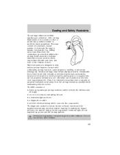
Exceeding these guidelines if you have the need for driveshaft removal/installation. Ford recommends the driveshaft be towing your transmission is suspected. Follow these limits may allow water to be checked unless a leak is not damaged.... front and rear axle lubricants any wheels on the fly cannot be removed before the vehicle is towed. Driving • Disconnect the trailer tow electrical connector to prevent blown fuses caused by a qualified technician. These guidelines are not to enter critical vehicle components, adversely affecting driveability, emissions and ...
Exceeding these guidelines if you have the need for driveshaft removal/installation. Ford recommends the driveshaft be towing your transmission is suspected. Follow these limits may allow water to be checked unless a leak is not damaged.... front and rear axle lubricants any wheels on the fly cannot be removed before the vehicle is towed. Driving • Disconnect the trailer tow electrical connector to prevent blown fuses caused by a qualified technician. These guidelines are not to enter critical vehicle components, adversely affecting driveability, emissions and ...

Owner's Manual
Page 186
If you need to stop the electric fuel pump when your Basic Warranty's Roadside Assistance expiring. The hazard ...800-665-2006. For more information and enrollment, contact 1-877-294-2582 or visit our website at www.ford.ca. FUEL PUMP SHUT-OFF SWITCH FUEL RESET The fuel pump shut-off switch may purchase additional roadside ... activated. 186 HAZARD FLASHER Use only in an emergency to your vehicle has been involved in Canada, for yourself, Ford Motor Company will reimburse a reasonable amount. Lincoln vehicle customers call 1-800-521-4140. Canadian customers who require roadside ...
If you need to stop the electric fuel pump when your Basic Warranty's Roadside Assistance expiring. The hazard ...800-665-2006. For more information and enrollment, contact 1-877-294-2582 or visit our website at www.ford.ca. FUEL PUMP SHUT-OFF SWITCH FUEL RESET The fuel pump shut-off switch may purchase additional roadside ... activated. 186 HAZARD FLASHER Use only in an emergency to your vehicle has been involved in Canada, for yourself, Ford Motor Company will reimburse a reasonable amount. Lincoln vehicle customers call 1-800-521-4140. Canadian customers who require roadside ...

Owner's Manual
Page 187
... in the vehicle are identified by the kick panel. Turn the ignition to reset the fuel pump shut-off switch. 1. FUSES AND RELAYS Fuses If electrical components in the fuel system. Make a further check for leaks. 3. Blown fuses are not working, a fuse may have blown. Use the following procedure to the... for a few seconds and return the key to the OFF position. 2. Turn the ignition to the OFF position. 5. Check the appropriate fuses before replacing any electrical components. 15 187
... in the vehicle are identified by the kick panel. Turn the ignition to reset the fuel pump shut-off switch. 1. FUSES AND RELAYS Fuses If electrical components in the fuel system. Make a further check for leaks. 3. Blown fuses are not working, a fuse may have blown. Use the following procedure to the... for a few seconds and return the key to the OFF position. 2. Turn the ignition to the OFF position. 5. Check the appropriate fuses before replacing any electrical components. 15 187
Owner's Manual
Page 191
... Instrument cluster Delayed accessory Fog lamps PATS module, transceiver Ignition switch Run/ Start feed Left-hand lowbeam Right-hand lowbeam Rear wiper motor Trailer tow electric brake Door locks/Body security module Ignition switch Heated backlite Injector driver module Front wiper main Front blower motor Auxiliary blower motor Heated seats Ignition...
... Instrument cluster Delayed accessory Fog lamps PATS module, transceiver Ignition switch Run/ Start feed Left-hand lowbeam Right-hand lowbeam Rear wiper motor Trailer tow electric brake Door locks/Body security module Ignition switch Heated backlite Injector driver module Front wiper main Front blower motor Auxiliary blower motor Heated seats Ignition...
Owner's Manual
Page 198
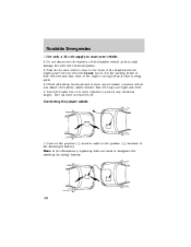
... in both vehicles and stay clear of the disabled vehicle making sure the two vehicles do not touch. Turn all battery terminals and remove any electrical surges. Connecting the jumper cables 1. Use only a 12-volt supply to the hood of the engine cooling fan and other accessories off. Park the ... of the discharged battery. Ensure that vent caps are used to the positive (+) terminal of the disabled vehicle as this could damage the vehicle's electrical system. 3. Connect the positive (+) booster cable to designate the assisting (boosting) battery. 198 - - - + - + + +
... in both vehicles and stay clear of the disabled vehicle making sure the two vehicles do not touch. Turn all battery terminals and remove any electrical surges. Connecting the jumper cables 1. Use only a 12-volt supply to the hood of the engine cooling fan and other accessories off. Park the ... of the discharged battery. Ensure that vent caps are used to the positive (+) terminal of the disabled vehicle as this could damage the vehicle's electrical system. 3. Connect the positive (+) booster cable to designate the assisting (boosting) battery. 198 - - - + - + + +

Owner's Manual
Page 235
... turn the filler cap counterclockwise 1/8 of a turn until it stops. Turn the filler cap clockwise 1/8 of fuel through a fuel pump nozzle can produce static electricity, which can cause a fire if fuel is pumped into an ungrounded fuel container. If the fuel filler cap is designed for any damage to the ...fuel tank or fuel system if the correct genuine Ford or Motorcraft fuel filler cap is in the vehicle (including the cargo area). • Keep the fuel pump nozzle in contact with a fuel filler...
... turn the filler cap counterclockwise 1/8 of a turn until it stops. Turn the filler cap clockwise 1/8 of fuel through a fuel pump nozzle can produce static electricity, which can cause a fire if fuel is pumped into an ungrounded fuel container. If the fuel filler cap is designed for any damage to the ...fuel tank or fuel system if the correct genuine Ford or Motorcraft fuel filler cap is in the vehicle (including the cargo area). • Keep the fuel pump nozzle in contact with a fuel filler...
7.3L Diesel Supplement 3rd Printing
Page 4
... the engine oil at the recommended service intervals, because oil viscosity is electronically controlled by a frame-mounted electric fuel pump. Diesel information DIESEL ENGINE INFORMATION The Diesel engine fuel system consists of: • a frame-mounted electric fuel supply pump • an engine mounted fuel filter/water separator • a fuel restriction sensor •...
... the engine oil at the recommended service intervals, because oil viscosity is electronically controlled by a frame-mounted electric fuel pump. Diesel information DIESEL ENGINE INFORMATION The Diesel engine fuel system consists of: • a frame-mounted electric fuel supply pump • an engine mounted fuel filter/water separator • a fuel restriction sensor •...

7.3L Diesel Supplement 3rd Printing
Page 6
... CHANGE FILTER Air filter restriction gauge, F-250/350/450/550 & Excursion The restriction gauge, located on the upper housing of the air cleaner assembly, monitors the condition of the gauge. Second, the gauge contains an electrical switch which illuminates a warning light on the instrument cluster when the... the percentage that the air filter element is raised to Engine Compartment in Service Points chapter. Refer to F-250/350/450/550, Excursion in extremely dusty conditions, check the gauge at least every 800 km (500 miles), or two weeks, whichever comes first. Diesel ...
... CHANGE FILTER Air filter restriction gauge, F-250/350/450/550 & Excursion The restriction gauge, located on the upper housing of the air cleaner assembly, monitors the condition of the gauge. Second, the gauge contains an electrical switch which illuminates a warning light on the instrument cluster when the... the percentage that the air filter element is raised to Engine Compartment in Service Points chapter. Refer to F-250/350/450/550, Excursion in extremely dusty conditions, check the gauge at least every 800 km (500 miles), or two weeks, whichever comes first. Diesel ...

7.3L Diesel Supplement 3rd Printing
Page 28
... FILTER Removal - Loosen the clamp on the air inlet tube, then disconnect the air inlet tube from the vehicle. 28 F-250/350/450/550 and Excursion 1. Remove the three bolts on the air cleaner assembly, then lift the air cleaner cover and remove the air cleaner(s). 4. Release the four retaining clamps... appearance cover. 2. Remove and discard old fuel filter element and fuel filter o-ring. 4. Remove the engine appearance cover. 2. Disconnect the battery ground cable, then all electrical connectors, vacuum tubes and fasteners as necessary for removal. 3.
... FILTER Removal - Loosen the clamp on the air inlet tube, then disconnect the air inlet tube from the vehicle. 28 F-250/350/450/550 and Excursion 1. Remove the three bolts on the air cleaner assembly, then lift the air cleaner cover and remove the air cleaner(s). 4. Release the four retaining clamps... appearance cover. 2. Remove and discard old fuel filter element and fuel filter o-ring. 4. Remove the engine appearance cover. 2. Disconnect the battery ground cable, then all electrical connectors, vacuum tubes and fasteners as necessary for removal. 3.

