Scheduled Maintenance Guide 3rd Printing
Page 8
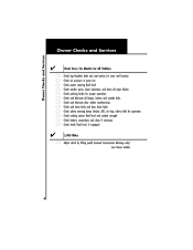
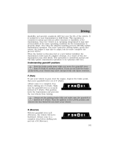
... and clean body and door drain holes safety warning lamps (brake, ABS, air bag, safety belt) for operation cooling system fluid level and coolant strength battery connections and clean if necessary clutch fluid level, if equipped 5,000 Miles Adjust clutch by lifting pedal (manual transmission Mustang only) (see Owner Guide) 8
... and clean body and door drain holes safety warning lamps (brake, ABS, air bag, safety belt) for operation cooling system fluid level and coolant strength battery connections and clean if necessary clutch fluid level, if equipped 5,000 Miles Adjust clutch by lifting pedal (manual transmission Mustang only) (see Owner Guide) 8
Scheduled Maintenance Guide 3rd Printing
Page 35
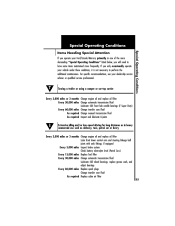
... your dealership service advisor or qualified service professional. Special Operating Conditions Special Operating Conditions Items Needing Special Attention If you operate your Ford/Lincoln/Mercury primarily in heavy commercial use such as delivery, taxi, patrol car or livery Every 3,000 miles or 3 months... front lower control arm and steering linkage ball joints with zerk fittings, if equipped Every 5,000 miles Inspect brake system Check battery electrolyte level (Patrol Cars) Every 15,000 miles Replace fuel filter Every 30,000 miles Change automatic transmission fluid Lubricate 4X2 wheel...
... your dealership service advisor or qualified service professional. Special Operating Conditions Special Operating Conditions Items Needing Special Attention If you operate your Ford/Lincoln/Mercury primarily in heavy commercial use such as delivery, taxi, patrol car or livery Every 3,000 miles or 3 months... front lower control arm and steering linkage ball joints with zerk fittings, if equipped Every 5,000 miles Inspect brake system Check battery electrolyte level (Patrol Cars) Every 15,000 miles Replace fuel filter Every 30,000 miles Change automatic transmission fluid Lubricate 4X2 wheel...
Owner Guide 4th Printing
Page 3
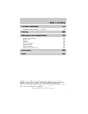
... storage and retrieval system or translation in whole or part is not permitted without incurring obligation. Copyright © 2002 Ford Motor Company 3 only) 219 228 Cleaning Maintenance and Specifications Engine compartment Engine oil Battery Fuel information Part numbers Refill capacities Lubricant specifications 229 236 238 241 248 255 278 279 282 Accessories Index...
... storage and retrieval system or translation in whole or part is not permitted without incurring obligation. Copyright © 2002 Ford Motor Company 3 only) 219 228 Cleaning Maintenance and Specifications Engine compartment Engine oil Battery Fuel information Part numbers Refill capacities Lubricant specifications 229 236 238 241 248 255 278 279 282 Accessories Index...
Owner Guide 4th Printing
Page 9
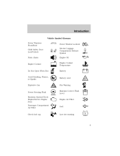
Introduction Vehicle Symbol Glossary Power Windows Front/Rear Child Safety Door Lock/Unlock Panic Alarm Engine Coolant Power Window Lockout Interior Luggage Compartment Release Symbol Engine Oil Engine Coolant Temperature Battery Do Not Open When Hot Avoid Smoking, Flames, or Sparks Explosive Gas Battery Acid Fan Warning Maintain Correct Fluid Level Engine Air Filter MAX MIN Power Steering Fluid Emission System/Check Engine/Service Engine Soon Passenger Compartment Air Filter Jack Check fuel cap Low tire warning 9
Introduction Vehicle Symbol Glossary Power Windows Front/Rear Child Safety Door Lock/Unlock Panic Alarm Engine Coolant Power Window Lockout Interior Luggage Compartment Release Symbol Engine Oil Engine Coolant Temperature Battery Do Not Open When Hot Avoid Smoking, Flames, or Sparks Explosive Gas Battery Acid Fan Warning Maintain Correct Fluid Level Engine Air Filter MAX MIN Power Steering Fluid Emission System/Check Engine/Service Engine Soon Passenger Compartment Air Filter Jack Check fuel cap Low tire warning 9
Owner Guide 4th Printing
Page 12
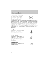
... your safety belts. Safety belt Illuminates to remind you to confirm that the air bags (front or side) are operational. Charging system Illuminates when the battery is not charging properly. 12 If the light fails to illuminate, continues to flash or remains on , continues to flash or fails to illuminate, have...
... your safety belts. Safety belt Illuminates to remind you to confirm that the air bags (front or side) are operational. Charging system Illuminates when the battery is not charging properly. 12 If the light fails to illuminate, continues to flash or remains on , continues to flash or fails to illuminate, have...
Owner Guide 4th Printing
Page 16
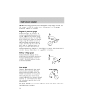
Battery voltage gauge Indicates battery voltage. If the pointer moves and stays outside the normal operating range, have your dealership or by a qualified technician. When refueling the vehicle from empty ...
Battery voltage gauge Indicates battery voltage. If the pointer moves and stays outside the normal operating range, have your dealership or by a qualified technician. When refueling the vehicle from empty ...
Owner Guide 4th Printing
Page 108
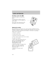
... the ignition in operating range can be up to be caused by one coin type three-volt lithium battery CR2032 or equivalent. Twist a thin coin between the two halves of new battery in the same orientation. Place the positive (+) side of the transmitter near the key ring. A...Press this control to the diagram inside the transmitter unit. 3. Refer to activate the alarm. Snap the two halves back together. 108 Replacing the battery The transmitter is powered by : • Weather conditions • Nearby radio towers • Structures around the vehicle • Other vehicles parked ...
... the ignition in operating range can be up to be caused by one coin type three-volt lithium battery CR2032 or equivalent. Twist a thin coin between the two halves of new battery in the same orientation. Place the positive (+) side of the transmitter near the key ring. A...Press this control to the diagram inside the transmitter unit. 3. Refer to activate the alarm. Snap the two halves back together. 108 Replacing the battery The transmitter is powered by : • Weather conditions • Nearby radio towers • Structures around the vehicle • Other vehicles parked ...

Owner Guide 4th Printing
Page 110
The system automatically turns off after the ignition has been turned to your vehicle is an engine immobilization system. The battery saver will shut off if: • they have been turned on top of the instrument panel. • When the ignition is in ...-THEFT SYSTEM (IF EQUIPPED) SecuriLock passive anti-theft system is used to indicate normal system functionality. If a problem occurs with non-Ford aftermarket remote start systems. Use of security protection. Locks and Security Illuminated entry The interior lamps illuminate when the remote entry system is in the...
The system automatically turns off after the ignition has been turned to your vehicle is an engine immobilization system. The battery saver will shut off if: • they have been turned on top of the instrument panel. • When the ignition is in ...-THEFT SYSTEM (IF EQUIPPED) SecuriLock passive anti-theft system is used to indicate normal system functionality. If a problem occurs with non-Ford aftermarket remote start systems. Use of security protection. Locks and Security Illuminated entry The interior lamps illuminate when the remote entry system is in the...
Owner Guide 4th Printing
Page 161
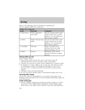
...someone. Always come to shift firmly. R (Reverse) With the gearshift lever in P (Park). Driving durability, and provide consistent shift feel . When the battery is at operating temperature it may take several shifts at the same operating condition for a new transmission to a complete stop before shifting into P (Park). ... brake pedal down while you do not hold the brake pedal down, your vehicle. Once the vehicle is disconnected or a new battery installed, the transmission must learn its optimum shift feel over the life of this, the transmission may shift firmly.
...someone. Always come to shift firmly. R (Reverse) With the gearshift lever in P (Park). Driving durability, and provide consistent shift feel . When the battery is at operating temperature it may take several shifts at the same operating condition for a new transmission to a complete stop before shifting into P (Park). ... brake pedal down while you do not hold the brake pedal down, your vehicle. Once the vehicle is disconnected or a new battery installed, the transmission must learn its optimum shift feel over the life of this, the transmission may shift firmly.
Owner Guide 4th Printing
Page 190
... excessive shifting, use a lower gear. Yellow Trailer left -hand turn signal 3. Circuit activated when brake pedal is depressed or when ignition is on a trip to battery's negative ground. 2.
... excessive shifting, use a lower gear. Yellow Trailer left -hand turn signal 3. Circuit activated when brake pedal is depressed or when ignition is on a trip to battery's negative ground. 2.
Owner Guide 4th Printing
Page 200
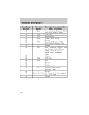
... Module (PCM) power diode, Ignition, PATS GEM, Radio Hazard flasher Auxiliary power socket Not used Clutch Pedal Position (CPP) switch, Starter interrupt relay Not used Battery saver relay, Auxiliary relay box, Restraint Central Module (RCM), Generic Electronic Module (GEM), Instrument cluster Not used GEM, Radio Radio Not used Not used Not...
... Module (PCM) power diode, Ignition, PATS GEM, Radio Hazard flasher Auxiliary power socket Not used Clutch Pedal Position (CPP) switch, Starter interrupt relay Not used Battery saver relay, Auxiliary relay box, Restraint Central Module (RCM), Generic Electronic Module (GEM), Instrument cluster Not used GEM, Radio Radio Not used Not used Not...
Owner Guide 4th Printing
Page 201
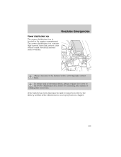
... Emergencies Power distribution box The power distribution box is located in the engine compartment. If the battery has been disconnected and reconnected, refer to the Battery section of electrical shock, always replace the cover to the Power Distribution Box before servicing high ...current fuses. To reduce risk of the Maintenance and specifications chapter. 201 Always disconnect the battery before reconnecting the battery or refilling fluid reservoirs. The power distribution box contains high-current fuses that protect your vehicle's main electrical systems ...
... Emergencies Power distribution box The power distribution box is located in the engine compartment. If the battery has been disconnected and reconnected, refer to the Battery section of electrical shock, always replace the cover to the Power Distribution Box before servicing high ...current fuses. To reduce risk of the Maintenance and specifications chapter. 201 Always disconnect the battery before reconnecting the battery or refilling fluid reservoirs. The power distribution box contains high-current fuses that protect your vehicle's main electrical systems ...
Owner Guide 4th Printing
Page 213
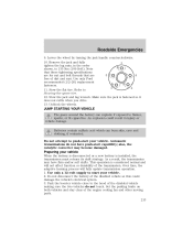
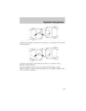
Use only Ford recommended (1/2-20) replacement fasteners. 5 2 11. Stow the flat tire. Refer to flames, sparks, or lit cigarettes. JUMP STARTING YOUR VEHICLE The gases around the battery can burn skin, eyes and clothing, if contacted. Automatic transmissions do not touch. This operation is considered ...normal and will fully update transmission operation. 1. Roadside Emergencies 9. Do not attempt to start your vehicle When the battery is disconnected or a new battery is fastened so it does not rattle when you drive. 13. also, the catalytic converter may have push-start ...
Use only Ford recommended (1/2-20) replacement fasteners. 5 2 11. Stow the flat tire. Refer to flames, sparks, or lit cigarettes. JUMP STARTING YOUR VEHICLE The gases around the battery can burn skin, eyes and clothing, if contacted. Automatic transmissions do not touch. This operation is considered ...normal and will fully update transmission operation. 1. Roadside Emergencies 9. Do not attempt to start your vehicle When the battery is disconnected or a new battery is fastened so it does not rattle when you drive. 13. also, the catalytic converter may have push-start ...
Owner Guide 4th Printing
Page 214
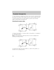
... both vehicles to the positive (+) terminal of the assisting battery. 214 - - - + - + + + Connecting the jumper cables 1. Connect the positive (+) booster cable to protect any excessive corrosion before you attach the battery cables. Connect the other accessories off. Roadside Emergencies 4. ... other end of the positive (+) cable to designate the assisting (boosting) battery. 2. Ensure that vent caps are used to the positive (+) terminal of the discharged battery. Turn all battery terminals and remove any electrical surges. Note: In the illustrations, lightning bolts...
... both vehicles to the positive (+) terminal of the assisting battery. 214 - - - + - + + + Connecting the jumper cables 1. Connect the positive (+) booster cable to protect any excessive corrosion before you attach the battery cables. Connect the other accessories off. Roadside Emergencies 4. ... other end of the positive (+) cable to designate the assisting (boosting) battery. 2. Ensure that vent caps are used to the positive (+) terminal of the discharged battery. Turn all battery terminals and remove any electrical surges. Note: In the illustrations, lightning bolts...
Owner Guide 4th Printing
Page 215
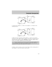
Connect the negative (-) cable to the negative (-) terminal of the battery to be jumped. Ensure that surround the battery. 5. Do not connect the end of the second cable to an exposed metal part of both engines, or any fuel delivery system parts. - - - + + + + ...- 215 Make the final connection of the negative (-) cable to the negative (-) terminal of the assisting battery. 4. A spark may cause an explosion of the gases that the cables are clear of fan blades, belts, moving parts of the stalled vehicle's engine, away...
Connect the negative (-) cable to the negative (-) terminal of the battery to be jumped. Ensure that surround the battery. 5. Do not connect the end of the second cable to an exposed metal part of both engines, or any fuel delivery system parts. - - - + + + + ...- 215 Make the final connection of the negative (-) cable to the negative (-) terminal of the assisting battery. 4. A spark may cause an explosion of the gases that the cables are clear of fan blades, belts, moving parts of the stalled vehicle's engine, away...
Owner Guide 4th Printing
Page 216
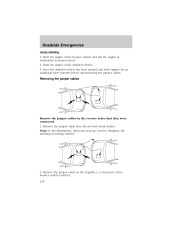
... cable from the ground metal surface. Remove the jumper cable on the negative (-) connection of the booster vehicle's battery. 216 - - - - + + + + Note: In the illustrations, lightning bolts are used to designate the assisting (boosting) battery. 2. Roadside Emergencies Jump starting 1. Once the disabled vehicle has been started, run the engine at moderately increased speed...
... cable from the ground metal surface. Remove the jumper cable on the negative (-) connection of the booster vehicle's battery. 216 - - - - + + + + Note: In the illustrations, lightning bolts are used to designate the assisting (boosting) battery. 2. Roadside Emergencies Jump starting 1. Once the disabled vehicle has been started, run the engine at moderately increased speed...
Owner Guide 4th Printing
Page 217
Remove the jumper cable from the positive (+) terminal of the booster vehicle's battery. 4. After the disabled vehicle has been started and the jumper cables removed, allow it to idle for several minutes so the engine computer can relearn its idle conditions. - - - + + - + + 217 Remove the jumper cable from the positive (+) terminal of the disabled vehicle's battery. Roadside Emergencies 3.
Remove the jumper cable from the positive (+) terminal of the booster vehicle's battery. 4. After the disabled vehicle has been started and the jumper cables removed, allow it to idle for several minutes so the engine computer can relearn its idle conditions. - - - + + - + + 217 Remove the jumper cable from the positive (+) terminal of the disabled vehicle's battery. Roadside Emergencies 3.
Owner Guide 4th Printing
Page 236
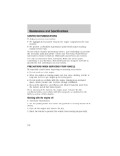
...8226; Automatic transmission: 1. Check your vehicle. • Do not work on a hot engine. • When the engine is securely latched in the Battery section of this chapter. Working with the engine running , make sure that loose clothing, jewelry or long hair does not get caught up in moving... SERVICE RECOMMENDATIONS To help you service your vehicle. Motorcraft parts are sure you are designed and built to prevent the vehicle from the battery and all fuel related parts. Block the wheels to provide the best performance in your vehicle: • We highlight do-it-yourself...
...8226; Automatic transmission: 1. Check your vehicle. • Do not work on a hot engine. • When the engine is securely latched in the Battery section of this chapter. Working with the engine running , make sure that loose clothing, jewelry or long hair does not get caught up in moving... SERVICE RECOMMENDATIONS To help you service your vehicle. Motorcraft parts are sure you are designed and built to prevent the vehicle from the battery and all fuel related parts. Block the wheels to provide the best performance in your vehicle: • We highlight do-it-yourself...
Owner Guide 4th Printing
Page 237
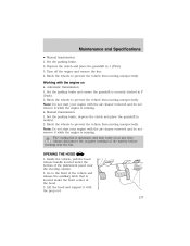
... and do not remove it with the air cleaner removed and do not remove it while the engine is located under the bottom of the battery before working near the steering column. 2. OPENING THE HOOD 1. Go to prevent the vehicle from moving unexpectedly.
... and do not remove it with the air cleaner removed and do not remove it while the engine is located under the bottom of the battery before working near the steering column. 2. OPENING THE HOOD 1. Go to prevent the vehicle from moving unexpectedly.
Owner Guide 4th Printing
Page 238
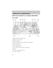
Maintenance and Specifications IDENTIFYING COMPONENTS IN THE ENGINE COMPARTMENT 2.3L I4 engine 1. Engine oil dipstick 4. Power distribution box 8. Battery 10. Engine coolant reservoir 3. Brake fluid reservoir 7. Power steering fluid reservoir 11. Windshield washer fluid reservoir 2. Engine oil filler cap 6. Clutch fluid reservoir (manual transmission) 9. Air filter assembly 238 Transmission fluid dipstick (automatic transmission) 5.
Maintenance and Specifications IDENTIFYING COMPONENTS IN THE ENGINE COMPARTMENT 2.3L I4 engine 1. Engine oil dipstick 4. Power distribution box 8. Battery 10. Engine coolant reservoir 3. Brake fluid reservoir 7. Power steering fluid reservoir 11. Windshield washer fluid reservoir 2. Engine oil filler cap 6. Clutch fluid reservoir (manual transmission) 9. Air filter assembly 238 Transmission fluid dipstick (automatic transmission) 5.


