
Owner Guide 6th Printing
Page 4
Vehicle Symbol Glossary Safety Alert See Owner's Guide Fasten Safety Belt Air Bag-Front Air Bag-Side Child Seat Installation Warning Brake System Brake Fluid Non-Petroleum Based AdvanceTrac Child Seat Child Seat Tether Anchorage Anti-Lock Brake System Traction Control Master Lighting Switch Hazard Warning Flasher Fog Lamps-Front Fuse Compartment Fuel Pump Reset Windshield Defrost/Demist Power Windows Front/Rear Windshield Wash/Wipe Rear Window Defrost/Demist 4 Introduction These are some of the symbols you may see on your vehicle.
Vehicle Symbol Glossary Safety Alert See Owner's Guide Fasten Safety Belt Air Bag-Front Air Bag-Side Child Seat Installation Warning Brake System Brake Fluid Non-Petroleum Based AdvanceTrac Child Seat Child Seat Tether Anchorage Anti-Lock Brake System Traction Control Master Lighting Switch Hazard Warning Flasher Fog Lamps-Front Fuse Compartment Fuel Pump Reset Windshield Defrost/Demist Power Windows Front/Rear Windshield Wash/Wipe Rear Window Defrost/Demist 4 Introduction These are some of the symbols you may see on your vehicle.
Owner Guide 6th Printing
Page 164
... air bag sensors increasing the risk of injury. Please refer to service, repair, or modify the air bag supplemental restraint systems or its fuses. Seating and safety restraints Always transport children 12 years old and under in serious arm fractures or other injuries. Do not modify the front... end of additional equipment. 164 Never place your Ford or Lincoln Mercury dealer. Do not attempt to the Body Builders Layout Book for instructions about the appropriate installation of the vehicle. Do ...
... air bag sensors increasing the risk of injury. Please refer to service, repair, or modify the air bag supplemental restraint systems or its fuses. Seating and safety restraints Always transport children 12 years old and under in serious arm fractures or other injuries. Do not modify the front... end of additional equipment. 164 Never place your Ford or Lincoln Mercury dealer. Do not attempt to the Body Builders Layout Book for instructions about the appropriate installation of the vehicle. Do ...

Owner Guide 6th Printing
Page 168
... Safety Canopy could injure you as it deploys from the headliner. All occupants of the inflatable Safety Canopy. 168 Do not lean your Ford or Lincoln Mercury dealer. Do not attempt to follow these instructions may come into contact with a deploying Safety Canopy. Seating and safety restraints Safety... the event of a collision. See your head on a vehicle containing a Safety Canopy. Failure to service, repair, or modify the Safety Canopy system, its fuses, the A, B, or C pillar trim, or the headliner on the door.
... Safety Canopy could injure you as it deploys from the headliner. All occupants of the inflatable Safety Canopy. 168 Do not lean your Ford or Lincoln Mercury dealer. Do not attempt to follow these instructions may come into contact with a deploying Safety Canopy. Seating and safety restraints Safety... the event of a collision. See your head on a vehicle containing a Safety Canopy. Failure to service, repair, or modify the Safety Canopy system, its fuses, the A, B, or C pillar trim, or the headliner on the door.

Owner Guide 6th Printing
Page 195
.... Apply the brake and shift into the access hole to the access hole in the Roadside emergencies chapter. Return the cover plate (rotate clockwise) to Fuses and relays in the open position. 4. Refer to the closed position. Do not drive your vehicle until it is lined up to override the brake.... Start the vehicle. Insert a tool (or screw driver) into Neutral. 5. Driving 3. Rotate the access panel (counterclockwise) with a flat head screw driver until you verify that a fuse has blown or the vehicle's brakelamps are working. 195
.... Apply the brake and shift into the access hole to the access hole in the Roadside emergencies chapter. Return the cover plate (rotate clockwise) to Fuses and relays in the open position. 4. Refer to the closed position. Do not drive your vehicle until it is lined up to override the brake.... Start the vehicle. Insert a tool (or screw driver) into Neutral. 5. Driving 3. Rotate the access panel (counterclockwise) with a flat head screw driver until you verify that a fuse has blown or the vehicle's brakelamps are working. 195

Owner Guide 6th Printing
Page 227
... in the vehicle are identified by pushing in the passenger's foot well, by the kick panel. Check the appropriate fuses before replacing any electrical components. 15 227 Blown fuses are not working, a fuse may have blown. Use the following procedure to the OFF position. 5. Turn the ignition to the OFF position.... 2. FUSES AND RELAYS Fuses If electrical components in the fuel system. If no fuel leak is located in on the reset button. 4. Roadside emergencies The fuel pump ...
... in the vehicle are identified by pushing in the passenger's foot well, by the kick panel. Check the appropriate fuses before replacing any electrical components. 15 227 Blown fuses are not working, a fuse may have blown. Use the following procedure to the OFF position. 5. Turn the ignition to the OFF position.... 2. FUSES AND RELAYS Fuses If electrical components in the fuel system. If no fuel leak is located in on the reset button. 4. Roadside emergencies The fuel pump ...

Owner Guide 6th Printing
Page 228
... Pink Tan Brown Red Blue Yellow Natural Green - - - - - Green Orange Red Blue Tan Natural Cartridge Fuse link maxi cartridge fuses Blue Blue - - Standard fuses Grey Violet Pink Tan Brown Red Blue Yellow Natural Green - - - - - Maxi fuses Yellow - Using a fuse with one that has the specified amperage rating. Pink Pink Green Green Red Red - Yellow - Roadside...
... Pink Tan Brown Red Blue Yellow Natural Green - - - - - Green Orange Red Blue Tan Natural Cartridge Fuse link maxi cartridge fuses Blue Blue - - Standard fuses Grey Violet Pink Tan Brown Red Blue Yellow Natural Green - - - - - Maxi fuses Yellow - Using a fuse with one that has the specified amperage rating. Pink Pink Green Green Red Red - Yellow - Roadside...

Owner Guide 6th Printing
Page 229
Roadside emergencies Passenger compartment fuse panel The fuse panel is located below the instrument panel on the fuse panel box. 6 7 8 9 10 11 1 2 3 4 5 12 13 14 15 16 17 18 19 20 21 22 23 24 25 26 27 28 29 30 229 To remove a fuse use the fuse puller tool provided on the driver's side.
Roadside emergencies Passenger compartment fuse panel The fuse panel is located below the instrument panel on the fuse panel box. 6 7 8 9 10 11 1 2 3 4 5 12 13 14 15 16 17 18 19 20 21 22 23 24 25 26 27 28 29 30 229 To remove a fuse use the fuse puller tool provided on the driver's side.

Owner Guide 6th Printing
Page 230
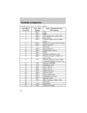
... Rating 30A 20A 20A 5A 15A 10A 15A - - 10A Passenger Compartment Fuse Panel Description Memory seat module Heated seats, Moonroof Radio, Amplifier, Power antenna, DVD Front wiper module Flasher relay (Turn, hazards) Right horn Heated mirrors Not ...
... Rating 30A 20A 20A 5A 15A 10A 15A - - 10A Passenger Compartment Fuse Panel Description Memory seat module Heated seats, Moonroof Radio, Amplifier, Power antenna, DVD Front wiper module Flasher relay (Turn, hazards) Right horn Heated mirrors Not ...
Owner Guide 6th Printing
Page 231
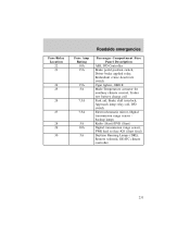
Roadside emergencies Fuse/Relay Location 22 23 Fuse Amp Rating 10A 15A Passenger Compartment Fuse Panel Description ABS, IVD Controller Brake pedal position switch, Driver brake applied relay, Redundant cruise deactivate switch Cigar lighter, OBD II Mode-Temperature actuator... Approach lamp relay coil, IVD switch Electrochromatic mirror, Digital transmission range sensor backup lamps Radio (Start)/DVD (Start) Digital transmission range sensor, PWR feed to fuse #28 (Start feed) Daytime Running Lamps (DRL), Remote solenoid, DEATC climate controller 24 25 15A 5A 26 7.5A 27 7.5A 28 29 30 5A ...
Roadside emergencies Fuse/Relay Location 22 23 Fuse Amp Rating 10A 15A Passenger Compartment Fuse Panel Description ABS, IVD Controller Brake pedal position switch, Driver brake applied relay, Redundant cruise deactivate switch Cigar lighter, OBD II Mode-Temperature actuator... Approach lamp relay coil, IVD switch Electrochromatic mirror, Digital transmission range sensor backup lamps Radio (Start)/DVD (Start) Digital transmission range sensor, PWR feed to fuse #28 (Start feed) Daytime Running Lamps (DRL), Remote solenoid, DEATC climate controller 24 25 15A 5A 26 7.5A 27 7.5A 28 29 30 5A ...
Owner Guide 6th Printing
Page 232
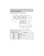
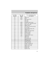
Fuse/Relay Location Relay 1 Relay 2 Relay 3 Relay 4 Relay 5 Relay 6 Relay 7 Description Flasher relay Rear defrost Delayed accessory relay Open Battery saver Open Open 232 To access the relays you must remove the passenger compartment fuse panel. Roadside emergencies Passenger compartment fuse panel (top side) These relays are located on the reverse side of the passenger compartment fuse panel.
Fuse/Relay Location Relay 1 Relay 2 Relay 3 Relay 4 Relay 5 Relay 6 Relay 7 Description Flasher relay Rear defrost Delayed accessory relay Open Battery saver Open Open 232 To access the relays you must remove the passenger compartment fuse panel. Roadside emergencies Passenger compartment fuse panel (top side) These relays are located on the reverse side of the passenger compartment fuse panel.

Owner Guide 6th Printing
Page 233
... reconnecting the battery or refilling fluid reservoirs. If the battery has been disconnected and reconnected, refer to the Power Distribution Box before servicing high current fuses. To reduce risk of electrical shock, always replace the cover to the Battery section of the Maintenance and specifications chapter. 233 Roadside emergencies Power distribution...
... reconnecting the battery or refilling fluid reservoirs. If the battery has been disconnected and reconnected, refer to the Power Distribution Box before servicing high current fuses. To reduce risk of electrical shock, always replace the cover to the Battery section of the Maintenance and specifications chapter. 233 Roadside emergencies Power distribution...
Owner Guide 6th Printing
Page 234
... Location 1 2 3 4 5 6 7 8 9 10 11 12 13 14 15 16 17 18 19 20 21 22 23 24 25 26 27 Fuse Amp Rating 60A** 30A** 20A** 30A** 40A** 60A** 20A** - 20A** 30A** 40A** 50A** 40A** 10A* 15A* 15A* 20A* 20A* 20A** 30A** 30A** 20A** 30A** 20A* - ...
... Location 1 2 3 4 5 6 7 8 9 10 11 12 13 14 15 16 17 18 19 20 21 22 23 24 25 26 27 Fuse Amp Rating 60A** 30A** 20A** 30A** 40A** 60A** 20A** - 20A** 30A** 40A** 50A** 40A** 10A* 15A* 15A* 20A* 20A* 20A** 30A** 30A** 20A** 30A** 20A* - ...
Owner Guide 6th Printing
Page 235
... 34 35 36 37 38 39 40 41 42 43 44 45 46 47 48 49 50 51 52 53 54 55 56 57 58 Fuse Amp Rating 20A* 60A** 20A** - - 30A** 30A** 20A** 40A** 15A* 15A* 15A* 15A* 15A* 10A* 10A* 15A* 5A* 20A Power Distribution Box Description Horn relay...
... 34 35 36 37 38 39 40 41 42 43 44 45 46 47 48 49 50 51 52 53 54 55 56 57 58 Fuse Amp Rating 20A* 60A** 20A** - - 30A** 30A** 20A** 40A** 15A* 15A* 15A* 15A* 15A* 10A* 10A* 15A* 5A* 20A Power Distribution Box Description Horn relay...

Owner Guide 6th Printing
Page 236
... Relay Box The relay box is located on the rear passenger side quarter trim panel. The relays are coded as follows: Fuse/Relay Location Relay 14 Relay 15 Relay 16 Relay 17 Relay 18 Relay 19 Relay 20 236 Description Not used Trailer tow park lamps Trailer ...
... Relay Box The relay box is located on the rear passenger side quarter trim panel. The relays are coded as follows: Fuse/Relay Location Relay 14 Relay 15 Relay 16 Relay 17 Relay 18 Relay 19 Relay 20 236 Description Not used Trailer tow park lamps Trailer ...
Owner Guide 6th Printing
Page 237
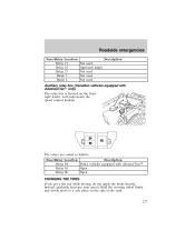
Hold the steering wheel firmly and slowly move to a safe place on the front right fender well underneath the speed control module. Roadside emergencies Fuse/Relay Location Relay 21 Relay 22 Relay 23 Diode 3 Diode 4 Description Not used Approach lamps Not used Not used Not used Auxiliary relay box... you get a flat tire while driving, do not apply the brake heavily. Instead, gradually decrease your speed. The relays are coded as follows: Fuse/Relay Location Description Relay 64 Police vehicles equipped with AdvanceTracி only) The relay box is located on the side of the road. 237
Hold the steering wheel firmly and slowly move to a safe place on the front right fender well underneath the speed control module. Roadside emergencies Fuse/Relay Location Relay 21 Relay 22 Relay 23 Diode 3 Diode 4 Description Not used Approach lamps Not used Not used Not used Auxiliary relay box... you get a flat tire while driving, do not apply the brake heavily. Instead, gradually decrease your speed. The relays are coded as follows: Fuse/Relay Location Description Relay 64 Police vehicles equipped with AdvanceTracி only) The relay box is located on the side of the road. 237

Owner Guide 6th Printing
Page 328
flex fuel vehicle (FFV) ...280, 283 Fuses ...227, 229 G Garage door opener ...101, 103 Gas cap (see Fuel cap) ...9, 285 Gas mileage (see Fuel economy) ...286 Gauges ...14 battery voltage gauge ...16 ...
flex fuel vehicle (FFV) ...280, 283 Fuses ...227, 229 G Garage door opener ...101, 103 Gas cap (see Fuel cap) ...9, 285 Gas mileage (see Fuel economy) ...286 Gauges ...14 battery voltage gauge ...16 ...
Owner Guide 6th Printing
Page 330
... alarm feature, remote entry system ...118 Parking brake ...189 Parts (see Motorcraft parts) ...304 Pedals (see Power adjustable foot pedals) ...33 Power distribution box (see Fuses) ...233 Power door locks ...110 Power mirrors ...111 Power point ...113 Power steering ...193 fluid, checking and adding ...268
... alarm feature, remote entry system ...118 Parking brake ...189 Parts (see Motorcraft parts) ...304 Pedals (see Power adjustable foot pedals) ...33 Power distribution box (see Fuses) ...233 Power door locks ...110 Power mirrors ...111 Power point ...113 Power steering ...193 fluid, checking and adding ...268
