
Owner's Manual
Page 35
5. When the tongues or chest clip are securely buckled, the color green appears. 32 Figure 4: Shoulder safety belt placement on the child NOTE: Read the following steps carefully to Figure 4. When either of the tongues or the chest clip is unbuckled, the color red appears in the window. Refer to become familiar with the indicator windows located on the child seat and position the shoulder belts over each safety belt tongue and the chest clip. Place the child on each shoulder.
5. When the tongues or chest clip are securely buckled, the color green appears. 32 Figure 4: Shoulder safety belt placement on the child NOTE: Read the following steps carefully to Figure 4. When either of the tongues or the chest clip is unbuckled, the color red appears in the window. Refer to become familiar with the indicator windows located on the child seat and position the shoulder belts over each safety belt tongue and the chest clip. Place the child on each shoulder.

Owner's Manual
Page 53
...the vehicle seat and attaches to an anchoring point. Other manufacturers offer the tether strap as described below . RWARNING Use only the tether attachment locations shown below . Attaching Safety Seats With Tether Straps Some manufacturers make safety seats that include a tether strap that the seat is held securely...using the built-in place. Make sure the tongue is used. 50 The tether anchor may not perform properly if the wrong mounting location is securely fastened to the front passenger or second row seats by pulling on the back of your child safety seat for the ...
...the vehicle seat and attaches to an anchoring point. Other manufacturers offer the tether strap as described below . RWARNING Use only the tether attachment locations shown below . Attaching Safety Seats With Tether Straps Some manufacturers make safety seats that include a tether strap that the seat is held securely...using the built-in place. Make sure the tongue is used. 50 The tether anchor may not perform properly if the wrong mounting location is securely fastened to the front passenger or second row seats by pulling on the back of your child safety seat for the ...

Owner's Manual
Page 54
Safety Restraints Three tether strap anchor locations have been provided in your vehicle. They are as follows: Tether strap anchor locations s FRONT PASSENGER SEATING POSITION - You must use the tether strap anchor location provided on the back of the seat cushion frame. (Refer to Figure 1.) 51
Safety Restraints Three tether strap anchor locations have been provided in your vehicle. They are as follows: Tether strap anchor locations s FRONT PASSENGER SEATING POSITION - You must use the tether strap anchor location provided on the back of the seat cushion frame. (Refer to Figure 1.) 51

Owner's Manual
Page 55
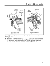
Figure 1: Tether anchor location - Front passenger seat s SECOND ROW BENCH (if equipped) SEATING POSITION - You must use one of the two tether strap anchor locations (one each side) provided on the back of the seat cushion. (Refer to Figures 2 and 3.) Figure 2: Tether anchor location - second row bench seat (with built-in child safety seat) 52
Figure 1: Tether anchor location - Front passenger seat s SECOND ROW BENCH (if equipped) SEATING POSITION - You must use one of the two tether strap anchor locations (one each side) provided on the back of the seat cushion. (Refer to Figures 2 and 3.) Figure 2: Tether anchor location - second row bench seat (with built-in child safety seat) 52
Owner's Manual
Page 56
Safety Restraints Figure 3: Tether anchor location - second row bench seat (without built-in child safety seat) s SECOND ROW BUCKET (if equipped) SEATING POSITION - You must use the tether strap anchor location provided on the back of the seat cushion. (Refer to Figure 4.) 53
Safety Restraints Figure 3: Tether anchor location - second row bench seat (without built-in child safety seat) s SECOND ROW BUCKET (if equipped) SEATING POSITION - You must use the tether strap anchor location provided on the back of the seat cushion. (Refer to Figure 4.) 53

Owner's Manual
Page 57
Tilt the seat from side to tug the seat forward. Once you have attached the safety seat, test the seat before you place the child in a collision or sudden stop greatly increases. 54 RWARNING If the safety seat is used. Figure 4: Tether anchor location - second row bucket seat RWARNING Only use the tether attachment hole locations shown in place. The tether anchor may not perform properly if the wrong mounting location is not anchored properly, the risk of a child being injured in it. Also try to side. Check to see if the belt holds the seat in the illustrations.
Tilt the seat from side to tug the seat forward. Once you have attached the safety seat, test the seat before you place the child in a collision or sudden stop greatly increases. 54 RWARNING If the safety seat is used. Figure 4: Tether anchor location - second row bucket seat RWARNING Only use the tether attachment hole locations shown in place. The tether anchor may not perform properly if the wrong mounting location is not anchored properly, the risk of a child being injured in it. Also try to side. Check to see if the belt holds the seat in the illustrations.

Owner's Manual
Page 64
Have all the passengers get out of the vehicle and call the local fire department or a towing service. 61 Starting Your Windstar What To Do If The Engine Does Not Start Fuel Pump Shut-Off Switch If the engine cranks but does not start or does not ... try to stop the fuel pump when your vehicle. The fuel pump shut-off switch may have been triggered. Fuel pump shut-off switch is located behind the jack access cover under the jack in a substantial jolt. Once the shut-off switch reset button...
Have all the passengers get out of the vehicle and call the local fire department or a towing service. 61 Starting Your Windstar What To Do If The Engine Does Not Start Fuel Pump Shut-Off Switch If the engine cranks but does not start or does not ... try to stop the fuel pump when your vehicle. The fuel pump shut-off switch may have been triggered. Fuel pump shut-off switch is located behind the jack access cover under the jack in a substantial jolt. Once the shut-off switch reset button...

Owner's Manual
Page 99
They are: s Trip distance s Instantaneous fuel economy s Average fuel economy s Distance to empty s Average speed 97 Each bar on the display represents 200 RPM. The tachometer Fuel Computer The Electronic Cluster Fuel Computer display is located under the tachometer and consists of the cluster displays the approximate engine speed in the right center of a menu and a digital display. Warning Lights and Gauges Tachometer The electronic bar graph tachometer in revolutions per minute (RPM). The fuel computer can display five different functions.
They are: s Trip distance s Instantaneous fuel economy s Average fuel economy s Distance to empty s Average speed 97 Each bar on the display represents 200 RPM. The tachometer Fuel Computer The Electronic Cluster Fuel Computer display is located under the tachometer and consists of the cluster displays the approximate engine speed in the right center of a menu and a digital display. Warning Lights and Gauges Tachometer The electronic bar graph tachometer in revolutions per minute (RPM). The fuel computer can display five different functions.

Owner's Manual
Page 100
... the menu. The displays remain in the chosen units until you switch them again, even after you choose the function displayed by the three buttons located to the top of the fuel computer buttons is displayed. Fuel Computer Buttons The fuel computer functions are controlled by the fuel computer. After it...
... the menu. The displays remain in the chosen units until you switch them again, even after you choose the function displayed by the three buttons located to the top of the fuel computer buttons is displayed. Fuel Computer Buttons The fuel computer functions are controlled by the fuel computer. After it...
Owner's Manual
Page 104
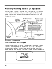
The auxiliary warning module Traction Control Active Light This light comes on when the Traction Control system begins applying and releasing the brakes and adjusting the engine characteristics to the right of the steering wheel. Auxiliary Warning Module (If equipped) An additional bank of indicator and warning lights is normal. 102 You may feel some steering changes and hear some noise, but this module are described and illustrated below. The light(s) located in this is located above the driver's side vent, just to limit a wheelspin condition.
The auxiliary warning module Traction Control Active Light This light comes on when the Traction Control system begins applying and releasing the brakes and adjusting the engine characteristics to the right of the steering wheel. Auxiliary Warning Module (If equipped) An additional bank of indicator and warning lights is normal. 102 You may feel some steering changes and hear some noise, but this module are described and illustrated below. The light(s) located in this is located above the driver's side vent, just to limit a wheelspin condition.
Owner's Manual
Page 106
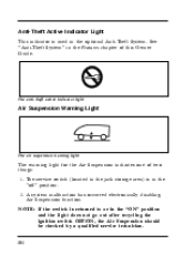
Anti-Theft Active Indicator Light This indicator is used in the "off" position. 2. The service switch (located in the jack storage area) is returned to or in the Features chapter of two things: 1. NOTE: If the switch is in the optional Anti-...
Anti-Theft Active Indicator Light This indicator is used in the "off" position. 2. The service switch (located in the jack storage area) is returned to or in the Features chapter of two things: 1. NOTE: If the switch is in the optional Anti-...
Owner's Manual
Page 109
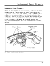
... An illustration of the register, defroster, and floor outlet locations follows. Each of these registers contain a louver assembly which can be manually adjusted to open or close each register. The defroster outlets are four registers ... that allows you to direct airflow UP, DOWN, LEFT and RIGHT. Each register in the instrument panel. Instrument Panel Controls Instrument Panel Registers There are located on the top of the instrument panel while the floor outlet is...
... An illustration of the register, defroster, and floor outlet locations follows. Each of these registers contain a louver assembly which can be manually adjusted to open or close each register. The defroster outlets are four registers ... that allows you to direct airflow UP, DOWN, LEFT and RIGHT. Each register in the instrument panel. Instrument Panel Controls Instrument Panel Registers There are located on the top of the instrument panel while the floor outlet is...

Owner's Manual
Page 114
... and Air Conditioning System Turning On the Heat You can heat the inside of your vehicle and defrost the windshield using the Function Selector Knob located in the control assembly in the instrument panel. The seven function selector modes are: MAX A/C, AC, Q (PANEL), S (PANEL/FLOOR), R (FLOOR), P (DEFROST/FLOOR), and V (DEFROST). When...
... and Air Conditioning System Turning On the Heat You can heat the inside of your vehicle and defrost the windshield using the Function Selector Knob located in the control assembly in the instrument panel. The seven function selector modes are: MAX A/C, AC, Q (PANEL), S (PANEL/FLOOR), R (FLOOR), P (DEFROST/FLOOR), and V (DEFROST). When...

Owner's Manual
Page 118
... is equipped with a rear climate control system, the rear seat occupants can control their own personal fan speed settings. Front passengers determine the temperature and location of the fan speed positions (Medium Low, Medium High, or High), air will not operate when the outside temperature is in either a heat or A/C mode...
... is equipped with a rear climate control system, the rear seat occupants can control their own personal fan speed settings. Front passengers determine the temperature and location of the fan speed positions (Medium Low, Medium High, or High), air will not operate when the outside temperature is in either a heat or A/C mode...

Owner's Manual
Page 119
... discharge (adjust registers) for front seat passengers, set the rear fan switch to the m (OFF) position. Instrument Panel Controls If an A/C mode is located on the instrument panel to the right of the steering column and below the climate control system. 117 Liftgate Window Features Rear Window Defogger (If... COOL (air-conditioned) air out of the rear window. Rear passengers do not have the ability to adjust the temperature or select the location of the airflow from both the inside and outside of the side and upper rear registers. NOTE: For maximum heating and cooling for comfort.
... discharge (adjust registers) for front seat passengers, set the rear fan switch to the m (OFF) position. Instrument Panel Controls If an A/C mode is located on the instrument panel to the right of the steering column and below the climate control system. 117 Liftgate Window Features Rear Window Defogger (If... COOL (air-conditioned) air out of the rear window. Rear passengers do not have the ability to adjust the temperature or select the location of the airflow from both the inside and outside of the side and upper rear registers. NOTE: For maximum heating and cooling for comfort.

Owner's Manual
Page 122
... on the headlamps, parking lamps, marker lamps, license plate lamps, tail lamps and instrument panel lights, use the headlamp control knob, to the left switches located in the ON or ACC positions. Power Quarter Vent Windows (If equipped) The power rear quarter vent windows operate with the ignition in the center...
... on the headlamps, parking lamps, marker lamps, license plate lamps, tail lamps and instrument panel lights, use the headlamp control knob, to the left switches located in the ON or ACC positions. Power Quarter Vent Windows (If equipped) The power rear quarter vent windows operate with the ignition in the center...

Owner's Manual
Page 123
Instrument Panel Controls The headlamp controls Fog Lamps (If equipped) The fog lamp switch is located on . 121 Fog lamp switch The fog lamps act as a supplement to the low beam headlamps under limited visibility conditions such as rain, snow, dust or fog and operate only when the low beam headlamps are on the center of the instrument panel.
Instrument Panel Controls The headlamp controls Fog Lamps (If equipped) The fog lamp switch is located on . 121 Fog lamp switch The fog lamps act as a supplement to the low beam headlamps under limited visibility conditions such as rain, snow, dust or fog and operate only when the low beam headlamps are on the center of the instrument panel.

Owner's Manual
Page 127
Once the slider knob is located to the right of the steering column next to the right, it controls how long the lamps stay on. Similarly, if you move the slide ...
Once the slider knob is located to the right of the steering column next to the right, it controls how long the lamps stay on. Similarly, if you move the slide ...
Owner's Manual
Page 128
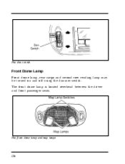
The front dome lamp is located overhead between the driver and front passenger seats. The front dome lamp and map lamps 126 The dim switch Front Dome Lamp Front dome lamp, rear cargo and second row reading lamp may be turned on and off using the dimmer switch.
The front dome lamp is located overhead between the driver and front passenger seats. The front dome lamp and map lamps 126 The dim switch Front Dome Lamp Front dome lamp, rear cargo and second row reading lamp may be turned on and off using the dimmer switch.
Owner's Manual
Page 129
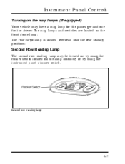
Instrument Panel Controls Turning on the map lamps (If equipped) Your vehicle may be turned on by using the instrument panel dimmer switch. Second row reading lamp 127 The rear cargo lamp is located overhead near the rear seating positions. Second Row Reading Lamp The second row reading lamp may have a map lamp for the passenger and one for the driver. The map lamps and switches are located on the lamp assembly or by using the rocker switch located on the front dome lamp.
Instrument Panel Controls Turning on the map lamps (If equipped) Your vehicle may be turned on by using the instrument panel dimmer switch. Second row reading lamp 127 The rear cargo lamp is located overhead near the rear seating positions. Second Row Reading Lamp The second row reading lamp may have a map lamp for the passenger and one for the driver. The map lamps and switches are located on the lamp assembly or by using the rocker switch located on the front dome lamp.


