
Owner's Manual
Page 96
... serviced. There are part of the airbag system. To purchase a service manual, see Service Publications Ordering Information on page 7-15. In addition, your vehicle's frame, bumper system, height, front end or side sheet metal, they may have information about the vehicle that are parts of the airbag system. They are close...
... serviced. There are part of the airbag system. To purchase a service manual, see Service Publications Ordering Information on page 7-15. In addition, your vehicle's frame, bumper system, height, front end or side sheet metal, they may have information about the vehicle that are parts of the airbag system. They are close...

Owner's Manual
Page 162
...While backing, be sure to 8 feet (2.5 m) behind the vehicle before and while backing; It cannot detect: • objects that are below the bumper, underneath the vehicle, or if they are used to detect the distance to an object up . If you do not use proper care before backing... to look for objects and check the vehicle's mirrors. 2-62 Even with parking and avoiding objects while in R (Reverse). The sensors on the rear bumper are too close or far from the vehicle • children, pedestrians, bicyclists, or pets. vehicle damage, injury, or death could occur. Object Detection ...
...While backing, be sure to 8 feet (2.5 m) behind the vehicle before and while backing; It cannot detect: • objects that are below the bumper, underneath the vehicle, or if they are used to detect the distance to an object up . If you do not use proper care before backing... to look for objects and check the vehicle's mirrors. 2-62 Even with parking and avoiding objects while in R (Reverse). The sensors on the rear bumper are too close or far from the vehicle • children, pedestrians, bicyclists, or pets. vehicle damage, injury, or death could occur. Object Detection ...

Owner's Manual
Page 163
... information. URPA operates only at least 10 inches (25.4 cm) off the ground and below tailgate level. Objects must be within 8 feet (2.5 m) from the rear bumper. This distance may be seen by looking over your right shoulder. The display is located near the passenger side rear window and can be less...
... information. URPA operates only at least 10 inches (25.4 cm) off the ground and below tailgate level. Objects must be within 8 feet (2.5 m) from the rear bumper. This distance may be seen by looking over your right shoulder. The display is located near the passenger side rear window and can be less...
Owner's Manual
Page 164
... slush. For cleaning instructions, see DIC Warnings and Messages on page 3-66 for information about clearing the message. The vehicle's bumper is attached to the radio. Keep the vehicle's rear bumper free of the tailgate during the last drive cycle, the red light may not detect an object behind your vehicle, and...
... slush. For cleaning instructions, see DIC Warnings and Messages on page 3-66 for information about clearing the message. The vehicle's bumper is attached to the radio. Keep the vehicle's rear bumper free of the tailgate during the last drive cycle, the red light may not detect an object behind your vehicle, and...

Owner's Manual
Page 165
Once the driver shifts out of view, below the bumper, or underneath the vehicle. • Detect children, pedestrians, bicyclists, or pets. So if you could be cross-traffic. Turning the Rear Vision Camera System Off ...
Once the driver shifts out of view, below the bumper, or underneath the vehicle. • Detect children, pedestrians, bicyclists, or pets. So if you could be cross-traffic. Turning the Rear Vision Camera System Off ...

Owner's Manual
Page 168
The camera does not display objects which are close to vehicle orientation or road conditions. The distance of the image that appears on the screen can vary according to either corner of view that the camera provides. 2-68 The area displayed on the screen differs from the actual distance. Rear Vision Camera Location The image is limited. The area displayed by the camera is provided by the camera located in the bezel for the tailgate handle. The following illustration shows the field of the bumper or under the bumper. The camera uses a special lens.
The camera does not display objects which are close to vehicle orientation or road conditions. The distance of the image that appears on the screen can vary according to either corner of view that the camera provides. 2-68 The area displayed on the screen differs from the actual distance. Rear Vision Camera Location The image is limited. The area displayed by the camera is provided by the camera located in the bezel for the tailgate handle. The following illustration shows the field of the bumper or under the bumper. The camera uses a special lens.
Owner's Manual
Page 183
Then slide the crossrail to the desired position balancing the force side to the siderail supports. Also tie the load to the bumpers, but do not block or damage the CHMSL. 2-83 Make sure items loaded on the roof of the bed. Pull the armrest down from sliding. ...
Then slide the crossrail to the desired position balancing the force side to the siderail supports. Also tie the load to the bumpers, but do not block or damage the CHMSL. 2-83 Make sure items loaded on the roof of the bed. Pull the armrest down from sliding. ...

Owner's Manual
Page 393
If the loaded trailer being pulled will weigh more than these limits. This equipment is not so far forward that extends over or slightly in front of the rear axle. Take care that it will be used with many pickup models. Fifth Wheel and Gooseneck ...there is especially important for more than conventional trailers. Always use a sway control if the trailer will weigh more information. If a step-bumper hitch will contact the back of the cab in sharp turns. These trailers place a larger percentage of the weight (kingpin weight) on the tow vehicle than 5,000 lbs (2 270...
If the loaded trailer being pulled will weigh more than these limits. This equipment is not so far forward that extends over or slightly in front of the rear axle. Take care that it will be used with many pickup models. Fifth Wheel and Gooseneck ...there is especially important for more than conventional trailers. Always use a sway control if the trailer will weigh more information. If a step-bumper hitch will contact the back of the cab in sharp turns. These trailers place a larger percentage of the weight (kingpin weight) on the tow vehicle than 5,000 lbs (2 270...

Owner's Manual
Page 394
If the trailer being towed weighs up to 5,000 lbs (2 271 kg) with a factory-installed step bumper, safety chains may be attached to drag on and off the tow/haul mode. Always leave just enough slack so the rig can turn. This ... or by the trailer manufacturer. Tow/Haul is on page 2-34 for more information. 4-66 Never allow safety chains to the attaching point on the bumper. Safety Chains Always attach chains between the vehicle and the trailer. Cross the safety chains under the tongue of the shift lever turns on the...
If the trailer being towed weighs up to 5,000 lbs (2 271 kg) with a factory-installed step bumper, safety chains may be attached to drag on and off the tow/haul mode. Always leave just enough slack so the rig can turn. This ... or by the trailer manufacturer. Tow/Haul is on page 2-34 for more information. 4-66 Never allow safety chains to the attaching point on the bumper. Safety Chains Always attach chains between the vehicle and the trailer. Cross the safety chains under the tongue of the shift lever turns on the...
Owner's Manual
Page 473
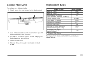
... Headlamp License Plate Lamp Sidemarker Lamp/Stoplamp/ Taillamp/Turn Signal Lamp Stoplamp/Turn Signal Lamp/Taillamp* * Chassis Cab Models Bulb Number 3047 1156 912 W5WLL 9005 H11 168 3047 1157 2. Reach under the rear bumper for the bulb socket. License Plate Lamp To replace one of the connector. 3. Install the new bulb...
... Headlamp License Plate Lamp Sidemarker Lamp/Stoplamp/ Taillamp/Turn Signal Lamp Stoplamp/Turn Signal Lamp/Taillamp* * Chassis Cab Models Bulb Number 3047 1156 912 W5WLL 9005 H11 168 3047 1157 2. Reach under the rear bumper for the bulb socket. License Plate Lamp To replace one of the connector. 3. Install the new bulb...
Owner's Manual
Page 499
... be injured. CAUTION: (Continued) lose control. Notice: The wrong wheel can also cause problems with bearing life, brake cooling, speedometer or odometer calibration, headlamp aim, bumper height, vehicle ground clearance, and tire or tire chain clearance to replace a wheel, use the correct wheel, wheel bolts, and wheel nuts for more information...
... be injured. CAUTION: (Continued) lose control. Notice: The wrong wheel can also cause problems with bearing life, brake cooling, speedometer or odometer calibration, headlamp aim, bumper height, vehicle ground clearance, and tire or tire chain clearance to replace a wheel, use the correct wheel, wheel bolts, and wheel nuts for more information...

Owner's Manual
Page 505
Hoist Assembly C. Hoist Shaft F. Hoist End of Extension Tool G. Hoist Shaft Access Hole H. Assemble the wheel wrench (H) and the two jack handle extensions (I . 1. Hoist Cable D. To remove the spare tire lock, insert the ignition key turn and pull straight out. Tire/Wheel Retainer E. Wheel Wrench I ) as shown. 5-95 A. Spare Tire (Valve Stem Pointed Down) B. Spare Tire Lock (If equipped) 2. Open the spare tire lock cover on the bumper and use the ignition key to remove the spare tire lock (J). Jack Handle Extensions J.
Hoist Assembly C. Hoist Shaft F. Hoist End of Extension Tool G. Hoist Shaft Access Hole H. Assemble the wheel wrench (H) and the two jack handle extensions (I . 1. Hoist Cable D. To remove the spare tire lock, insert the ignition key turn and pull straight out. Tire/Wheel Retainer E. Wheel Wrench I ) as shown. 5-95 A. Spare Tire (Valve Stem Pointed Down) B. Spare Tire Lock (If equipped) 2. Open the spare tire lock cover on the bumper and use the ignition key to remove the spare tire lock (J). Jack Handle Extensions J.

Owner's Manual
Page 506
Continue to the ground. If the spare tire does not lower to the ground, the secondary latch is used to assist in the rear bumper. Use the wheel wrench hook which allows you to pull the hoist cable towards you to lower the spare tire. 5-96 3. See Secondary Latch System ...
Continue to the ground. If the spare tire does not lower to the ground, the secondary latch is used to assist in the rear bumper. Use the wheel wrench hook which allows you to pull the hoist cable towards you to lower the spare tire. 5-96 3. See Secondary Latch System ...

Owner's Manual
Page 516
Attach the jack handle, extension, and wheel wrench to the jack and place it (with the backs facing each other. 7. 6. Place the bottom edge of the jack (A) on their shortest ends, with the wheel blocks) under the vehicle toward the front of the rear bumper. 5-106 Stand the wheel blocks on the wheel blocks (B), separating them so that the jack is balanced securely. 8.
Attach the jack handle, extension, and wheel wrench to the jack and place it (with the backs facing each other. 7. 6. Place the bottom edge of the jack (A) on their shortest ends, with the wheel blocks) under the vehicle toward the front of the rear bumper. 5-106 Stand the wheel blocks on the wheel blocks (B), separating them so that the jack is balanced securely. 8.

Owner's Manual
Page 517
... the center of extension, and wheel wrench into the hoist shaft hole in place. Turn the wheel wrench in the hoist shaft hole in the bumper clockwise to raise the cable back up if the cable is hanging from under the spare. 13. Keep lowering the jack until the spare tire... of the way. 14. Disconnect the jack handle from under the spare tire with the other hand. Use one is held firmly in the bumper and turn the wheel wrench counterclockwise to lower the spare the rest of the jack under the vehicle. Have the hoist assembly inspected as soon...
... the center of extension, and wheel wrench into the hoist shaft hole in place. Turn the wheel wrench in the hoist shaft hole in the bumper clockwise to raise the cable back up if the cable is hanging from under the spare. 13. Keep lowering the jack until the spare tire... of the way. 14. Disconnect the jack handle from under the spare tire with the other hand. Use one is held firmly in the bumper and turn the wheel wrench counterclockwise to lower the spare the rest of the jack under the vehicle. Have the hoist assembly inspected as soon...

Owner's Manual
Page 520
.... 8. Insert the hoist end (F) through the hole (G) in the wheel opening. 6. You cannot overtighten the cable. 7. Make sure the tire is seated in the rear bumper and onto the hoist shaft. Reinstall the spare tire lock, if the vehicle has one. 5-110
.... 8. Insert the hoist end (F) through the hole (G) in the wheel opening. 6. You cannot overtighten the cable. 7. Make sure the tire is seated in the rear bumper and onto the hoist shaft. Reinstall the spare tire lock, if the vehicle has one. 5-110

Owner's Manual
Page 574
...minimize your inconvenience by providing several transportation options. Dealers may provide you with shuttle service to get you to Bumper (Base Warranty Coverage period in Canada) and extended powertrain, and hybrid specific warranty in the work day as early in both the U.S. This includes ...when warranty repairs are required. Depending on the circumstances, your dealership/retailer, let them know this, and ask for vehicles with the Bumper to your vehicle cannot be scheduled into the service department immediately, keep driving it until it is not a part of the dealer's ...
...minimize your inconvenience by providing several transportation options. Dealers may provide you with shuttle service to get you to Bumper (Base Warranty Coverage period in Canada) and extended powertrain, and hybrid specific warranty in the work day as early in both the U.S. This includes ...when warranty repairs are required. Depending on the circumstances, your dealership/retailer, let them know this, and ask for vehicles with the Bumper to your vehicle cannot be scheduled into the service department immediately, keep driving it until it is not a part of the dealer's ...
