Sony HCD-SH2000 Support Question
Sony HCD-SH2000 Support Question
Find answers below for this question about Sony HCD-SH2000.Need a Sony HCD-SH2000 manual? We have 1 online manual for this item!
Question posted by peet on August 26th, 2014
Sony Hcd-sh2000 Playig Ipod
when we play the ipod we can only play via the tv connection as the ub device does not regonize the ipod
Current Answers
Related Sony HCD-SH2000 Manual Pages
Service Manual - Page 1
... model
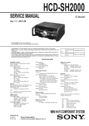
MINI HI-FI COMPONENT SYSTEM
9-890-576-02 2011I08-1 © 2011.09
Sony Corporation
Published by Sony EMCS (Malaysia) PG Tec...HCD-SH2000
SERVICE MANUAL
E Model
Ver. 1.1 2011.09
• HCD-SH2000 is the tuner, USB, CD and amplifier section in FST-SH2000/LBT-SH2000.
• "WALKMAN" and "WALKMAN" logo are registered trademarks of Sony Corporation. • MPEG Layer-3 audio...
Service Manual - Page 2
...is suitable.
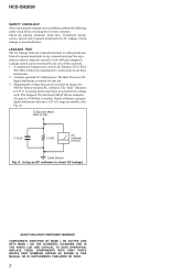
SAFETY-RELATED COMPONENT WARNING! REPLACE THESE COMPONENTS WITH SONY PARTS WHOSE PART NUMBERS APPEAR AS SHOWN IN THIS MANUAL OR IN SUPPLEMENTS PUBLISHED BY SONY.
2 Follow the manufacturers...methods. 1. The Simpson 250 and Sanwa SH-63Trd are suitable. (See Fig.
HCD-SH2000
SAFETY CHECK-OUT After correcting the original service problem, perform the following safety check ...
Service Manual - Page 3
... VOLUME LED, BOTTON LED AND TUNER Board 50
5-36. AUDIO-IN Board 51 5-37. AUDIO-IN Board 51 5-38. Chassis Section 68 6-5. HCD-SH2000
TABLE OF CONTENTS
1. DISASSEMBLY 2-1. Side Panel A, Side Panel B and Top Panel Section ........ 6 2-2. DMB21 Board 8 2-5. DIAGRAMS 5-1. Block Diagram - Printed Wiring Board
- MAIN Board (Component Side) (Suffix 11 20 5-6. Schematic Diagram...
Service Manual - Page 4
...ON LASER DIODE EMISSION CHECK The laser beam on this model is included in MPEG 1 Audio Layer 3 format.
2) A logical format of files and folders on CD-ROMs,..., exchange the entire MD (AU) ASSY.
4
HCD-SH2000
Ver. 1.1
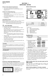
SECTION 1 SERVICING NOTES
Notes on chip component replacement • Never reuse a disconnected chip component. • Notice that enables adding of data using...
Service Manual - Page 5
MAIN Board (Component Side) - Repair after distinguishing each type set to doing the repair referring to "SECTION 2 DISASSEMBLY". disc
- HCD-SH2000
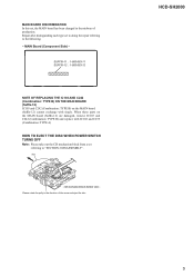
5 When these parts on the MAIN board (Suffix-12) cannot exchange with IC102 and C239 (Combination: TYPE A)
HOW TO EJECT THE DISC WHEN POWER ...
Service Manual - Page 6
...
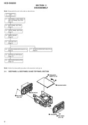
1 four screws (3.5 x 16)
3 side panel A 2
5
6 side panel B 4 four screws (3.5 x 16)
6 SWITCHING REGULATOR (Page 10)
Note: Follow the disassembly procedure in the order as shown below. HCD-SH2000
SECTION 2 DISASSEMBLY
Note: Disassemble the unit in the numerical order given. 2-1.
Service Manual - Page 7
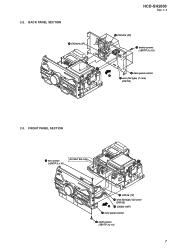
BACK PANEL SECTION
4 CN1404 (3P)
HCD-SH2000
Ver. 1.1
3 CN1405 (3P)
1 twelve screws (+BVTP 3 x 10)
6 back panel section 5
2 wire (flat type) (7 core) (CN703)
2-3. 2-2. FRONT PANEL SECTION
1 two screws (+BVTP 3 x10)
(for SAF, EA only)
3 CN106 (7P) 4 wire (flat type) (23 core)
(CN105) 6 5 CN300 (14P) 7 front panel section
2 eight screws (+BVTP 3 x10)
7
Service Manual - Page 8
... 3 x 10)
2 cover CDM top
3 three screws (+BVTP 3 x 10)
4 CD MECHANISM DECK BLOK
5 two screws (+BVTP 3 x 10)
6 cover CDM bottom
7 two screws (+BVTP 3 x 10)
8 CDM bracket
8 HCD-SH2000
Ver. 1.1
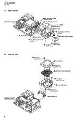
2-4. CDM SECTION
(for SAF, EA only)
8 wire (flat type) (7P core) (CN202/CN203)
7 wire (flat type) (24 core) (CN101) qd shield plate bottom DMB21...
Service Manual - Page 9
...)
5 Solder the short-land.
HCD-SH2000
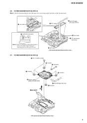
2-6. CD MECHANISM DECK BLOCK (2)
1 four insulator screws
5 insulator 3 connector
5 insulator
5 insulator
6 device, optical (KHM-313CAB/CZRP)
2 7 belt (MOT)
4 wire (flat type) (24 core) 5 insulator
- CD MECHANISM DECK BLOCK (1) Note 1 : Before disconnecting the wire (flat type) (24 core) of short-land after connecting the wire (flat type) (24...
Service Manual - Page 10
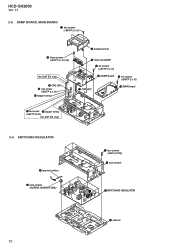
... 9 six screws (+BVTP 3 x 10)
7 CN3 (6P)
q; SWITCHING REGULATOR
3saranet cushion 4 nine screws
(SCREW, WASHER (M3))
1 four screws (+BV3 (3-CR))
2 sub chassis
5SWITCHING REGULATOR
6 chassis
10 HCD-SH2000
Ver. 1.1
2-8. DAMP BOARD, MAIN BOARD
1 two screws (+BVTP 3 x 10)
3 three screws (+BVTT 3 x 12 (S))
(for SAF, EA only)
2-9.
Service Manual - Page 11
...button and [PRESET EQ] button
simultaneously and hold 3 seconds. 2. The function is changed to TV and the volume is turned clockwise even slightly, the sound volume increases to turn on the &#... Press [FUNCTION] button repeatedly to view the destination information. 4. SECTION 3 TEST MODE
HCD-SH2000
PANEL TEST MODE This mode is turned counterclockwise. 8. COMMON TEST MODE This mode is...
Service Manual - Page 12
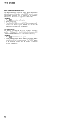
...all the factory use preset frequencies into FM 1-FM 20 and AM 1-AM 10. Press [PLAY/PAUSE] button and [EJECT] button simultaneously
for 3 seconds, message "FACTORY" appears on the... PRESET This mode is disc. Press @/1 button to turn on the fluorescent indicator tube. HCD-SH2000
DISC THEFT PREVENTION MODE This mode let prevent disc to be displayed on the system. 2. Procedure:...
Service Manual - Page 13
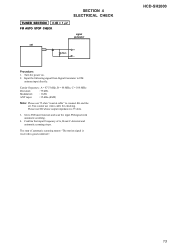
... MHz
Deviation
: 75 kHz
Modulation
: 1 kHz
ANT input
: 35 dBu (EMF)
Note: Please use 75 ohm "coaxial cable" to connect SG and the set
+ 75
- Please use video cable for checking. HCD-SH2000
13
Set to FM
antenna input directly.
Input the following signal from Signal Generator to FM tuner function and scan...
Service Manual - Page 14
HCD-SH2000
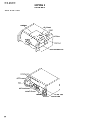
• Circuit Boards Location
SECTION 5 DIAGRAMS
DAMP board
MS-214 board TUNER MAIN board
DMB21 board SWITCHING REGULATOR
DISPLAY board BUTTON board
MIC board
BUTTON LED board VOLUME LED board USB board
VOLUME board AUDIO-IN board
14
Service Manual - Page 16
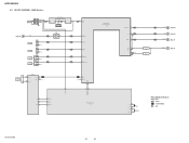
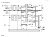
BLOCK DIAGRAM - HCD-SH2000
5-2. J1300 MIC IN
A (Page 15)
L-OUT
J1200
TV R-CH
J1201
PC
GAME AUDIO IN
DVD/SAT AUDIO IN
J500 L R L R
R-CH R-CH R-CH
IC1300 MIC AMP
5
7
3
1
RV1300
MIC LEVEL MIN MAX
IC501 OP AMP
5
7
46 MIC
39 GAME_L 43 TV IN-L 45 ...
X110 32.768kHz
R-ch is omitted due to same as L-ch. SIGNAL PATH
: AUDIO : TUNER (FM/AM) : MIC
HCD-SH2000
16
16
MAIN Section -
Service Manual - Page 17
... Q1476
DAMP FAN
M102 DC FAN
75
FAN LOCK DETECT
Q1447
SMPS FAN
FAN-EN 60
/FAN-LOCK 61
HCD-SH2000
17
17 D
Lch
(Page 16)
AMPLIFIER IC502
5 INPUT+ OUTPUT 1
7 OUTPUT INPUT+ 3
R-CH
...MUTE Q600
OP AMP IC600
5 INPUT+ OUTPUT 7
SIGNAL PATH
: AUDIO
MUTE Q207
51
/LINE-MUTE DAMP-CLK /DAMP-RESET
NO USE /SD-SLOW RESONANCE
D1403 D1435
HCD-SH2000
LOW SPEAKER IMPEDANCE USE 4ȍ
2 INA-
Service Manual - Page 18

...Q303
LED DRIVE Q301
100 USBB-LED-BLUE MTK-POWER-CTL 43
95 USBB-LED-RED
82 USBA-LED-BLUE
D1000 - HCD-SH2000
5-4. BLOCK DIAGRAM -
PANEL, POWER SUPPLY Section - D1005 (ILLUMINATION LED)
D1256 - S1013
CN705 3
L 4
LED ... SPK-L-LED-BLUE
PCONT-MAIN 63 PCONT-SUB 59
54 SPK-R-LED-RED 55 SPK-R-LED-BLUE
HCD-SH2000
AVDD +5V DVDD +5V
RF +3.3V
+3.3V REGULATOR
IC107
TU +3.3V VBUS +5V
LED...
Service Manual - Page 19

... 10 MΩ).
F : AUDIO E : USB f : TUNER J : AUDIO (DIGITAL)
• Abbreviation E2... mark : TUNER < > : CD PLAY
* : Impossible to ground
under no-...Component Side) the parts face are indicated.
Q BCE
These are in E model E51 : Chilean and Peruvian models EA : Saudi Arabia model MX : Mexican model MY : Malaysia model SAF : South African model
HCD-SH2000
19
19
HCD-SH2000...
Service Manual - Page 20

... SUFFIX-11 and SUFFIX-12. F
-&%
41&",&3
3
G
H
I
F700
3
1
3
1
J500
MAIN BOARD
(Component side)
DMB21
I BOARD CN4604 (Page 32)
DMB21
F BOARD CN602 (Page 32)
(CHASSIS)
DMB21
E BOARD CN1108 ...BOARD CN1000 (Page 45)
AUDIO-IN
H BOARD NO1200 (Page 51)
11 (11)
CN704
CN705
(CHASSIS)
G
DAMP BOARD CN1400 (Page 37)
B
DAMP BOARD CN1401 (Page 37)
J
HCD-SH2000
20
20
Note: Refer to...
Service Manual - Page 65
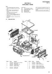
...+BVTP2.6 (3CR) HANDLE, COVER B
6
4-291-803-01 COVER, HOLE
7
4-277-991-01 PLATE, SONY
Remark
Ref. Replace only with no reference
number in the exploded views are not supplied. • Items marked "*"...#2
7-685-646-71 SCREW +BVTP 3X8 TYPE2 IT-3
Remark
65 MAIN SECTION
#1
10
HCD-SH2000
Ver. 1.1
The components identified by mark 0 or dotted line with mark 0 are seldom required for ...
Similar Questions

Hcd Sh2000 Sony
I have HCD SH 2000 it's has no audio out in any Chanel ( first it was on protection mode then now it...
I have HCD SH 2000 it's has no audio out in any Chanel ( first it was on protection mode then now it...
(Posted by Sehar517 1 year ago)

My Sony Hcd-sh2000 Does Not Switch On
Sony HCD-SH2000 does not switch ON but when the mains supply is unplugged the standby light flashes ...
Sony HCD-SH2000 does not switch ON but when the mains supply is unplugged the standby light flashes ...
(Posted by allieukamaraak 3 years ago)

Sony Radio Circuit Hcd-sh2000
Good Dayi Am Interesting In Buying A Radio Circuit Hcd-sh2000 (only) And Whats The Price?
Good Dayi Am Interesting In Buying A Radio Circuit Hcd-sh2000 (only) And Whats The Price?
(Posted by diel060781 4 years ago)

Parts Of Sony Hcd Sh2000
Dear Sir.I would like to ask you regarding Sony HCD-SH2000 electronic parts number Main Board. Damp...
Dear Sir.I would like to ask you regarding Sony HCD-SH2000 electronic parts number Main Board. Damp...
(Posted by rizwanbutt94 6 years ago)

Sony Mini Hifi Component System Mhc-ec909ip Wont Play Music From Ipod
(Posted by aaa35 10 years ago)