Sony HCD-SH2000 Support Question
Sony HCD-SH2000 Support Question
Find answers below for this question about Sony HCD-SH2000.Need a Sony HCD-SH2000 manual? We have 1 online manual for this item!
Question posted by rnrelectricalservices2019 on December 30th, 2020
Power Turn On Then Switched Off Mode
Hi as mentioned Sony System was working fine then it was suddently switched off then while turn it off it will be switched to off mode itself Please asist to rectify the issue
Current Answers
Answer #1: Posted by waelsaidani1 on December 30th, 2020 7:28 AM
waelsaidani1

Member since:
May 12th, 2013 Points: 19,501,787

Member since:
May 12th, 2013 Points: 19,501,787
Please follow the recommendation provided here by the manufacturer: https://www.sony.com/electronics/support/articles/00032613
Related Sony HCD-SH2000 Manual Pages
Service Manual - Page 1
... - 1,602 kHz (9 kHz step)
General Power requirements
AC 120 V - 240 V, 50/60 Hz Power consumption
320 W Dimensions (w/h/d) (excl. speakers)...HCD-SH2000
SERVICE MANUAL
E Model
Ver. 1.1 2011.09
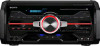
• HCD-SH2000 is the tuner, USB, CD and amplifier section in FST-SH2000/LBT-SH2000.
• "WALKMAN" and "WALKMAN" logo are registered trademarks of Sony Corporation. • MPEG Layer-3 audio...
Service Manual - Page 3
... (2/3 35 5-21. Printed Wiring Boards
- Schematic Diagram - VOLUME Board 46 5-32. Schematic Diagram - HCD-SH2000
TABLE OF CONTENTS
1. DISASSEMBLY 2-1. DMB21 Board 8 2-5. CD MECHANISM DECK BLOCK (1 9 2-7. RS SERVO, USB Section 15 5-2. MAIN Board (Component Side) (Suffix 11 20 5-6. Schematic Diagram - Schematic Diagram - Schematic Diagram - DAMP Board (1/4 39...
Service Manual - Page 4
...UNLEADED SOLDER Boards requiring use the procedure in the printed matter which compresses audio data. Ordinary soldering irons can be used but unleaded solder may also ... Lead-out regarded as a CLASS 1 LASER product.
HCD-SH2000
Ver. 1.1
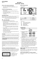
SECTION 1 SERVICING NOTES
Notes on chip component replacement • Never reuse a disconnected chip component. • Notice that the minus side of a...
Service Manual - Page 5
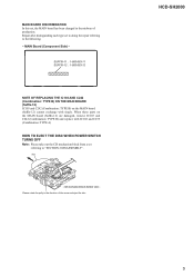
...Component Side) - Repair after distinguishing each type set , the MAIN board has been changed in the direction of production.
Please rotate the pully in the midway of the arrow and eject the disc. CD mechanism block bottom view - HCD-SH2000...: TYPE A)
HOW TO EJECT THE DISC WHEN POWER SWITCH TURNS OFF Note: Please take out the CD mechanism block from a set
referring to the following. -
Service Manual - Page 11
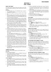
... fluorescent indicator tube. SECTION 3 TEST MODE
HCD-SH2000
PANEL TEST MODE This mode is set. All LEDs and segments in the data flash to turn off automatically. 4. When you press [SOUND ...indicator tube and all segments in the same manner as step 1, or disconnect the power cord.
Execute this mode, press @/1 button. 2. "COLD RESET" appears on the fluorescent indicator ...
Service Manual - Page 12
... CD function. 3. The message "LOCKED" or "UNLOCKED" displayed on the fluorescent indicator tube. FACTORY PRESET This mode is changed to turn on the system. 2. Press @/1 button to the minimum frequency. HCD-SH2000
DISC THEFT PREVENTION MODE This mode let prevent disc to load all the factory use preset frequencies into FM 1-FM 20 and AM...
Service Manual - Page 13
... cannot use 75 ohm "coaxial cable" to connect SG and the set
+ 75
-
Please use SG whose output impedance is received in good condition". Procedure: 1. Turn the power on. 2. HCD-SH2000
13
Service Manual - Page 14
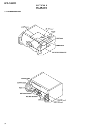
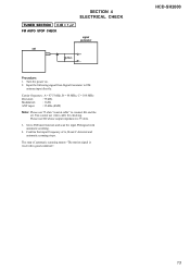
HCD-SH2000
• Circuit Boards Location
SECTION 5 DIAGRAMS
DAMP board
MS-214 board TUNER MAIN board
DMB21 board SWITCHING REGULATOR
DISPLAY board BUTTON board
MIC board
BUTTON LED board VOLUME LED board USB board
VOLUME board AUDIO-IN board
14
Service Manual - Page 17
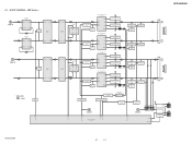
...+ INB+ AOUT BOUT
CEC DATA SWITCH Q1412
SWITCH Q1414
AMPLIFIER CONTROLLER IC1406
HO 14
3 IN 15 VB
VS 13 LO 11
COM 10
CEC DATA SWITCH Q1413
SWITCH Q1415
AMPLIFIER CONTROLLER IC1407
HO 14
...MUTE Q600
OP AMP IC600
5 INPUT+ OUTPUT 7
SIGNAL PATH
: AUDIO
MUTE Q207
51
/LINE-MUTE DAMP-CLK /DAMP-RESET
NO USE /SD-SLOW RESONANCE
D1403 D1435
HCD-SH2000
LOW SPEAKER IMPEDANCE USE 4ȍ
2 INA-
Service Manual - Page 18

...BLUE)
LED DRIVE Q303
LED DRIVE Q301
100 USBB-LED-BLUE MTK-POWER-CTL 43
95 USBB-LED-RED
82 USBA-LED-BLUE
D1000 - ...HCD-SH2000
AVDD +5V DVDD +5V
RF +3.3V
+3.3V REGULATOR
IC107
TU +3.3V VBUS +5V
LED +13.5V LED +13.5V
TD FL TUBE
M +9V VM +9V
D +9V
+5V REGULATOR
IC804
+3.3V REGULATOR
IC1601
SWITCHING DRIVER Q803
DC-DC CONVERTER TRANSFOMER T900
SWITCHING Q906, Q907
SWITCHING Q804
SWITCHING...
Service Manual - Page 24
...
12
0 JL150 50
0
AUDIO-CLK 49
JL149
0 48
JL148
0 AUDIO-DATA 47
JL147
0 FLASH-MEMORY 46
JL146
HUB-VBUS-DET 45 3.2 JL145
3.2
HUB-RESET 44
MTK-POWER-CTL 43 3.2 JL143
MTK-...C127 0.1
C128 0.1
POWER SWITCHING Q204
RT1N141C-TP-1
0
3.1
0
9
11
10
R258
R259
4.7k
10k
14
13.4
12.7
LED SWITCH
Q205
2SB1690TL
13.4
MAIN
3 BOARD (3/4) (Page 26)
12
58
13
HCD-SH2000
24
24 EA 4....
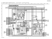
Service Manual - Page 25

...
3.3 3.3
C311 10
C411 0.1
R327 R326
220 45 220 44
HCD-SH2000
25
25
HCD-SH2000
11
12
13
14
15
15
16
17
18
MAIN
4 BOARD
...
21
3.1 R830 1.2k
R831 10k 9.0
8.3
0 0
R835 10k
R834 470
3.1
POWER CONTROL SWITCH
2.6
Q803
RT3N77M-TP-1
9.0 3.3 3.2
POWER CONTROL DRIVER
Q805 2SB1690TL
POWER CONTROL
DRIVER Q804
2SB1690TL
JL720 JL724 JL721 JL725 JL722 JL726 JL723
CN701 7P 7 VM (...
Service Manual - Page 27

... BB2R BB1R VOLINR TONEOUTR
15k
GAME IN-L
R739 27k
GAME
AUDIO IN
WHT
RED
L
R
C
D
MAIN
3
2 BOARD...
R817 0 R818 0
KIA7809AF/API 13.4 I
9 O
13.5
POWER SWITCH Q800
2SB1690TL
12.8
COM
C847
0
0.1
R673 15k
R676 10k R678...HCD-SH2000
27
27 SCHEMATIC DIAGRAM - MAIN BOARD (4/4) (Suffix 11) - • See page 54 for IC Block Diagrams.
1
2
3
4
5
6
7
8
HCD-SH2000...
Service Manual - Page 28

...
12
0 JL150 50
0
AUDIO-CLK 49
JL149
0 JL148 48
0 AUDIO-DATA 47
JL147
0 FLASH-MEMORY 46
JL146
HUB-VBUS-DET 45 3.2 JL145
3.2
HUB-RESET 44
MTK-POWER-CTL 43 3.2 JL143
MTK-...
C127 0.1
C128 0.1
POWER SWITCHING Q204
RT1N141C-TP-1
0
3.1
0
9
11
10
R258
R259
4.7k
10k
14
13.4
12.7
LED SWITCH
Q205
2SB1690TL
13.4
MAIN
3 BOARD (3/4) (Page 30)
12
58
13
HCD-SH2000
28
28
Service Manual - Page 29
...3.3 0
3.3 3.3 C311 10
C411 0.1
R327 220 45 R326 220 44
HCD-SH2000
29
29
HCD-SH2000
11
12
13
14
15
15
16
17
18
MAIN
4 BOARD
19
(3/4)... R830 1.2k
R831 10k 9.0
8.3
0 0
R835 10k
R834 470
3.1
POWER CONTROL SWITCH
2.6
Q803
RT3N77M-TP-1
9.0 3.3 3.2
POWER CONTROL DRIVER
Q805 2SB1690TL
POWER CONTROL
DRIVER Q804
2SB1690TL
JL720 JL724 JL721 JL725 JL722 JL726 JL723
CN701 7P 7 ...
Service Manual - Page 31

...
DVD/SAT
AUDIO IN
RED
L
R
33k 0.1
OUTPUT VCC INPUT- SCHEMATIC DIAGRAM - MAIN BOARD (4/4) (Suffix 12) - • See page 54 for IC Block Diagrams.
1
2
3
4
5
6
7
8
HCD-SH2000
9
10
...PC IN-L
IC803 IC803
+9V REG
R817 0 R818 0
KIA7809AF/API 13.4 I
9 O
13.5
POWER SWITCH Q800
2SB1690TL
12.8
COM
C847
0
0.1
R673 15k
R676 10k R678 100k
C676
0.1
R677
100k
R679
...
Service Manual - Page 61

...AUDIO-DATA
O Serial data output to audio signal processor, R2A15216FP
48
NO-USE
O Unused
49
AUDIO-CLK
O Serial data transfer clock signal output to audio signal processor, R2A15216FP
50
NO-USE
O Unused
51
/LINE-MUTE
O Muting Control Switch for all speaker mute control pin. Power...system clock input terminal (8MHz)
16
VCC
- HCD-SH2000
• IC Pin Function Descriptions MAIN BOARD ...
Service Manual - Page 63

...mode enable setting terminal Not used
I Reset signal input from the system controller "L": reset
I IR control signal input terminal Not used
I/O Two-way audio serial data with the USB controller
- Power...the optical pick-up block
- Power supply terminal (+3.3V)
I/O Two-way data bus with the SD-RAM
- Power supply terminal (+1.8V)
- HCD-SH2000
DMB21 BOARD (2/3) IC101 CXD9968R (LE...
Service Manual - Page 64

... I Limit detection switch input terminal O L/R sampling clock signal output to the A/D converter and D/A converter O Audio data output to the system controller
- Ground terminal
O Bank address signal output to the SD-RAM
O Address signal output to the SD-RAM
- Ground terminal
O Composite video signal output terminal Not used - Not used
- HCD-SH2000
Pin No. 69...
Service Manual - Page 70

...-21
SWITCH, TACTILE (FLANGER) SWITCH, TACTILE (+/1) SWITCH, TACTILE (ISOLATOR) SWITCH, TACTILE (SEARCH) SWITCH, TACTILE...components identified by reference number, please include the board name.
• Abbreviation E2 : 120V AC area in ohms. METAL: Metal-film resistor. When indicating parts by mark 0 or dotted line with part number specified.
HCD-SH2000
Ver. 1.1 AUDIO...
Similar Questions

Hcd Sh2000 Sony
I have HCD SH 2000 it's has no audio out in any Chanel ( first it was on protection mode then now it...
I have HCD SH 2000 it's has no audio out in any Chanel ( first it was on protection mode then now it...
(Posted by Sehar517 1 year ago)

Speaker Wire Connector
looking for part number: 1-839-129-11 and 1-839-128-2
looking for part number: 1-839-129-11 and 1-839-128-2
(Posted by Crsj1981 2 years ago)

Keeps Switching Mode
System keeps switching to Game mode, TV mode, only with the remote control I can switch it to CD, it...
System keeps switching to Game mode, TV mode, only with the remote control I can switch it to CD, it...
(Posted by flowertromp 8 years ago)

How To Turn Protected Mode Off On The Sony Component System
(Posted by saUsma 10 years ago)

My Display Light On My Sony 5 Master Hcd-mx500i Does Not Work.
(Posted by dawnwith3 11 years ago)