Sharp LC-26SH12U Support Question
Sharp LC-26SH12U Support Question
Find answers below for this question about Sharp LC-26SH12U - 26" LCD HDTV.Need a Sharp LC-26SH12U manual? We have 1 online manual for this item!
Question posted by kjnielsen215 on August 8th, 2010
Setting Up Tv Without Cable
Do I need a digital to analog converter boxes
Current Answers
Related Sharp LC-26SH12U Manual Pages
Service Manual - Page 1

S3701LC26SH12
LCD COLOR TELEVISION
MODEL LC-26SH12U
In the interests of user-safety (Required by safety regulations in some countries) the set should be restored ...; SERVICE MODE LIST ...C-1 • WHEN REPLACING EEPROM (MEMORY) IC C-2 • RE-WRITE FOR DIGITAL SOFT FIRMWARE C-3 • ELECTRICAL ADJUSTMENTS D-1~D-5 • TROUBLESHOOTING GUIDE E-1~E-5 • BLOCK DIAGRAM ...F-1~F-6 &#...
Service Manual - Page 2

... A1-1 KEEP THE NOTICES
As for safety which need special attentions, they are put these do not contact with the labels or seals on the TV. 3. PUT PARTS AND WIRES IN THE ORIGINAL POSITION... safety, or which has the same character. SERVICING NOTICES ON CHECKING
1. BE CAREFUL WITH THE LCD PANEL
Avoid a shock to the IC and Transistor). AVOID AN ELECTRIC SHOCK There is flowing....
Service Manual - Page 4

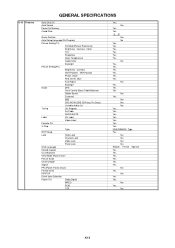
...Digital Frequency Analog
Preset CH Stereo/Dual TV Sound Tuner Sound Muting Video Signal
LCD Size / Visual Size LCD Type Number of Pixels
View Range
Position Size Impedance Max 10%(Typical) Analog Digital...
1.6 x 4.8 inch
4 ohm
5.0W + 5.0W
--- US System M
ATSC(8VSB)/QAM
1Tuner
US (W/CABLE)
2~69, 4A, A-5~A-1, A~I, J~W, W+1~W+84
44.00MHz
45.75MHz
41.25MHz
4.50MHz
No
US-Stereo
Yes...
Service Manual - Page 6
...
Auto Shut Off Auto Search Power On Memory Comb Filter
Game Position
Auto Setup(Language/CH Program)
Picture Setting(TV)
AV Mode(Picture Preference)
Brightness , Contrast , Color
Tint
Sharpness
Color Temperature
Cable Clear
Backlight
Picture Setting(PC)
Brightness , Contrast
HOR Position , VER Position
Phase, Clock
Red, Green, Blue
Auto Adjust
Backlight
Audio
MTS
Tone...
Service Manual - Page 7

...
Circuit Diagram
Antenna Change Plug
Service Facility List
Important Safeguard
Dew/AHC Caution Sheet
Quick Set-up Sheet
Battery
UM size x pcs
OEM Brand
AC Adapter
AC Cord (for AC Adapter)
AC Cord (Flat Polarity Plugs)
Cable Cramp
Stand
Stand Screw
Hexagon Wrench
AV Cord (2Pin-1Pin)
Registration Card (NDL Card)
300...
Service Manual - Page 8

...Analog Audio
Digital Audio Output
DC Jack (Center +)
VHF/UHF Antenna Input
Video Input 3
Audio Input 3
S - Input 3
Other Terminal
Rear
AC Inlet
Approx. W x D x H (mm)
Net (Approx.)
Net w/o Handle, Stand (Approx.)
Gross (Approx.)
Master Carton
Content
Material
Dimensions W x D x H(mm)
Description of Origin
Gift Box... SPECIFICATIONS
G-12 Interface
G-13 Set Size G-14 Weight G-15 ...
Service Manual - Page 13

...ON total hours are reset
such as the channel setting, and the POWER ON total hours. Can be...
SERVICE MODE LIST
This unit is provided with the following SERVICE MODES so you set factory initialization, the memories are displayed on the screen. DOWN (Minimum)
1...the appropriate condition. (See below chart.)
Set Condition
Power ON
Set Key
VOL.
C-1 Releasing of MEMORY IC.
Check...
Service Manual - Page 14
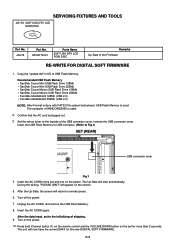
... out.
3. Turn off the power. 7. After the data input, set to the initializing of the set and turn on the set for the new DIGITAL SOFT FIRMWARE.
Copy the "update.dat" in CD to normal screen..... APJG176121
Parts Name
2007 USA DTV LCD ROM DISC
Remarks Up-Date of the USB connector cover, remove the USB connector cover. Set the minus driver to Fig.1)
SET (REAR)
USB connector cover
Fig.1 ...
Service Manual - Page 15
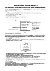
.../RIGHT button will turn off (return to STANDBY MODE) to the TV mode. 2. MICON Version Digital TV MICON Fimware
HCS CHK SUM : 07EA HRM CHK SUM : 9BD4 LCD PWR ON : 0000 OEC6088A_T039 DTV CA03B72232
FIG. 1
Initial setting data check sum. DOWN button on the set and Channel button (6) on the remote control for more than 2 seconds...
Service Manual - Page 16

...CENT 24 BAK LIGHT MAX 25 BAK LIGHT MIN 26 BRIGHT CENT 27 BRIGHT MAX 28 BRIGHT MIN 29 ... to select the options shown in Fig. 1-1.
Using the remote control, set the brightness and contrast to normal position. 9. Activate the adjustment mode display...mode display of the heat sink. Prepare the following measurement tools for TV, VIDEO1, VIDEO2, ColorStream HD, HDMI-0 and PC mode, press ...
Service Manual - Page 17

...CONTRAST 40". 4. Check if the picture is normal. 6. ELECTRICAL ADJUSTMENTS
2-2: WHITE BALANCE
1. Using the remote control, set the brightness and contrast to select the "R CUT OFF(N)", "B DRIVE(N)", "B CUT OFF(N)", "R DRIVE(C)", "R CUT... the channel button (26) on the remote control to select "R DRIVE(N)". 6. Press the INPUT button on the remote control to set to select "BRIGHT CENT...
Service Manual - Page 19

...Step No.)
Please check if the fixed values of each of the adjustment item is set correctly referring below. (AV/ANALOG TUNER/YUV/HDMI/PC/DIGITAL)
NO. Step No.
175
175
128
128
ADJ
ADJ
ADJ
ADJ
ADJ
ADJ
128...21 H POSI 60
22 V POSI 60
23 BAK LIGHT CENT
24 BAK LIGHT MAX
25 BAK LIGHT MIN
26 BRIGHT CENT
27 BRIGHT MAX
28 BRIGHT MIN
29 TINT
30 SHARP CENTER
31 SHARP MAX
32 SHARP MIN
33...
Service Manual - Page 26
...AN5832SA-E1V
Analog Tuner AUDIO... 2
DIGITAL AUDIO L/R
R G B 24bit
ATSC/CLEAR CABLE ASIC ...IC IC2401 X242
COMPONENT1 Y
COMPONENT_IN_1
IN
J701
COMPONENT1 U
AV3-13P2-31S1
COMPONENT1 V
PC1 R
D-SUM
IN
CP4201
PC1 G
D229FD015G107BY PC1 B
IN
CP3601 HDMI CONNECTOR
HDMI IN
SW IC703 NJM2584AM(TE1)
SW Y/G SW U/B SW V/R
X242 SPDIF
AD CONVERTER...LCD PANEL V2301
LK255T3LZ5AZ
F-1
F-2
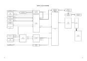
Service Manual - Page 27

POWER(DIGITAL PCB) BLOCK DIAGRAM
CP3401
1 SOUND +B 2
3 4
SOUND GND
5
6
GND
7
8 SW +12V 9
10 LCD+B
11 POWR_ON_H
12 LIGHTE_CTL
13 INVERTER_H
14
AT +...IC701 AN15853B-E1
Q3410 LCD +B RSQ035P03
PANEL V2301 LK255T3LZ5A
Q3406 P.CON +5V 2SB1132
AD CONVERTER IC6601
MST3583M-LF-110
SUBɹMICON IC101
OEC6088A
IC3403 BD3504FVM
Q3402 2SB1132
DTV +5V
ATSC/CLEAR CABLE ASIC IC IC2401 X242...
Service Manual - Page 34

...G
H 8
7
6 5
4
3
2
PCBDH0 CEF276
H
1
H-4 A
B
C
D
E
F
G
SDRAM SCHEMATIC DIAGRAM
8
(DIGITAL PCB)
7
6
5
4
3
FROM/TO POWER3 +3.3V
VDDC_1.0V
2
GND +2.5V_IO MEM[1.8V]
C2456 10 C
ATSC/CLEAR CABLE ASIC IC IC2401 X242 (5/14 SDRAM)
MEM_DQA0 MEM_DQA1 MEM_DQA2 MEM_DQA3 MEM_DQA4 MEM_DQA5 MEM_DQA6 MEM_DQA7 MEM_DQA8 MEM_DQA9 MEM_DQA10 MEM_DQA11 MEM_DQA12 MEM_DQA13 MEM_DQA14 MEM_DQA15
MEM_DQM0...
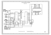
Service Manual - Page 35
...DIAGRAM
8
(DIGITAL PCB)
NFIO7 NFIO6 NFIO5 NFIO4 NFIO3 NFIO2 NFIO1 NFIO0
C2503 0.1 B
7
48 47 46 45 44 43 42 41 40 39 38 37 36 35 34 33 32 31 30 29 28 27 26 25
HY27US08281A-...R2511 4.7K
D 5.0
I2C_DATA
R2512
5V/3V LEVEL SHIFT 3.3
Q2404
S
2SK393800L
3.3 G
4.7K
D
5.0
I2C_CLK
ATSC/CLEAR CABLE ASIC IC IC2401 X242 (14/14 USB/SERIAL)
0 AE22 USBPA
0 AD22 USBNA
0 AD23 USBPB
0 AE23 USBNB
3.3 NC...
Service Manual - Page 39
... DHS DVS DEN
4
3
2
1
H-13
FROM/TO POWER3 LCD+B +3.3V
GND
NOTE: THIS SCHEMATIC DIAGRAM IS THE LATEST AT THE TIME OF PRINTING AND SUBJECT TO CHANGE WITHOUT NOTICE
A
B
C2588 0.1 B C2589 0.1 B
C
D
E
F
G
LVDS SHEMATIC DIAGRAM
(DIGITAL PCB)
C2591 0.1 B
C2593 0.1 B C2592 6.3V 220
V-S
C2594 0.1 B
3.3 Vcc
1
28 27 26 25 24 23 22 21 20 19 18...
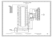
Service Manual - Page 41
...
1
CEF276
H
H-18 A
B
C
D
E
F
8
MICON SCHEMATIC DIAGRAM
(DIGITAL PCB)
G
H
8
REMOCON_IN C_SYNC
POWER_ON_MUTE_H INVETER_H LCD-H
7
7
KEY_B KEY_A
AFT
FROM/TO AV SWITCH/JACK C_SYNC
R103 4.7K R119 100... NC NC
0 REMOCON_IN
5.0
LED-H DTV_ON-H POWER_ON-H
C102 0.01 B
R104
100
33 32 31 30 29 28 27 26 25 24 23
44 43 42 41 40 39 38 37 36 35 34
5.0
VAREF
NC
NC
0
5.0
AVDD
NC
NC...
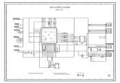
Service Manual - Page 49

...+12V
GND
8
7
SW+12V 9
9
SW+12V
GND
9
LCD+B
10
10
LCD+B
GND
10
POWER_ON_H 11
11 POWER_ON_H
Analog/Dimming 11
LIGHTE_CTL 12
12 LIGHTE_CTL
ON/OFF
12
INVETER_H 13
13...22
DTV+B
DTV+B
23
23
DTV+B
POWER PCB PCB240
CEF273
DIGITAL PCB PCBDH0 CEF276
20 RXIN0-
19 RXIN0+
GND
17 RXIN1...TO LCD PANEL CD7201
LCD PANEL V2301
E
21
GND
22
NC
23
GND
24
GND
25
GND
26
GND
...
Service Manual - Page 63

... CONNECTOR
CU145005 CU2E0601 CU256001 CU233301 CHRU1301
*** AC CORD ***
! CD3805
120Q119905 CORD SET AC
P201-2476-2
*** OTHERS ***
BT001 BT002
141R003018 BATTERY,MANGAN 141R003018 BATTERY,MANGAN... 070Y056003 SPEAKER
S0412F03 S0412F03
TM101
076B0MQ030 TRANSMITTER
ETR0088-010161
V2301
09E4126009 LCD
LK255T3LZ5AZ
RESISTOR RC CARBON RESISTOR
CAPACITORS CC CERAMIC CAPACITOR CE ALUMI ...
Similar Questions


V-chip Removal On My Sharp Tv
How to remove the V-CHIP setting on my LC-26SH12U Sharp TV .I lost the Password
How to remove the V-CHIP setting on my LC-26SH12U Sharp TV .I lost the Password
(Posted by hojess 8 years ago)

Will This Tv Receive A Digital Signal Without Using A Converter Box?
If the answer is yes, how do I set it up for digital?
If the answer is yes, how do I set it up for digital?
(Posted by Vitajack2 8 years ago)
How Do You Unlock A Sharp Television Mod 29s-fx10ldo You Need A Code
(Posted by dhanasarsoobhag 10 years ago)

Manual For Sharp Lc26sh12u Lcd Tv
We had the TV mounted on the wall, but now want to stand it up and my husband misplaced the stand. I...
We had the TV mounted on the wall, but now want to stand it up and my husband misplaced the stand. I...
(Posted by dooleytree 13 years ago)