Sharp LC-26SH12U Support Question
Sharp LC-26SH12U Support Question
Find answers below for this question about Sharp LC-26SH12U - 26" LCD HDTV.Need a Sharp LC-26SH12U manual? We have 1 online manual for this item!
Question posted by icu96 on May 9th, 2010
How To Connect To Stereo
Aloha
I have dvd connected to stereo just fine, ive been trying to figure how to listen to tv thru stereo(sony da30es) but no luck or is even possible.
Mahalo Joe
Current Answers
Related Sharp LC-26SH12U Manual Pages
Service Manual - Page 1

... K1-1~K2-9
This document has been published to be used for after sales service only. The contents are subject to change without notice. S3701LC26SH12
LCD COLOR TELEVISION
MODEL LC-26SH12U
In the interests of user-safety (Required by safety regulations in some countries) the set should be restored to its original condition and only...
Service Manual - Page 2

... positions, or whether there are the portions which is flowing.
3. Remove the antenna terminal on TV and turn
on the back of the heat sink. SERVICING NOTICES ON CHECKING
1. AVOID AN ELECTRIC... insulation material such as a mark, the designated parts must be found on the TV. 3. A1-1 BE CAREFUL WITH THE LCD PANEL
Avoid a shock to the IC and Transistor). And be more than 1M ...
Service Manual - Page 4

... Receive CH Intermediate Digital Frequency Analog
Preset CH Stereo/Dual TV Sound Tuner Sound Muting Video Signal
LCD Size / Visual Size LCD Type Number of Pixels
View Range
Position Size ...Resolution at DVD Mode
RGB Signal Audio Signal
Output Level Input Level Output Level
at DVD at TV
Digital Output Level
S/N Ratio at DVD (Weighted)
Harmonic Distortion
Frequency Response :
at DVD
at Video...
Service Manual - Page 9

... 2. 6. Remove the Angle Main. Remove the 2 screws 3. 7. Remove the Angle Hinge in the direction of arrow (B). 5. Holder Panel
Angle Main 3 3
3 3
2 Angle Main 2 2 LCD Block
2
Operation PCB
(B) Plate Button Ass'y
11 1
2
3 2
3
2 2
2
2
(C)
2
(A)
Angle Hinge
1 1
Holder Panel
(B) Angle Panel
(A)
Fig. 1-2
Fig. 1-4
B1-1 Disconnect the following connectors: (CP406, CP1001...
Service Manual - Page 10

... connector: (CP3401).
2. Remove the Digital PCB and Shield Digital in the direction of arrow (B).
1 2 3 2
4 4
Shield Digital
1-7: COVER LCD (Refer to Fig. 1-7)
1. Remove the 4 screws 2. 4. Remove the Cover LCD in the direction of arrow.
1 1
1 1
Cover LCD
LCD Panel
(A) Plate Jack
(B)
Digital PCB
Fig. 1-7
Fig. 1-5
1-6: POWER PCB (Refer to Fig. 1-5)
1. Remove the Power PCB in...
Service Manual - Page 14
... the Firmware
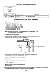
RE-WRITE FOR DIGITAL SOFT FIRMWARE
1.
Turn off the power. 7. SERVICING FIXTURES AND TOOLS
JG176 2007 USA DTV LCD ROM DISC
Ref. APJG176121
Parts Name
2007 USA DTV LCD ROM DISC
Remarks Up-Date of the USB connector cover, remove the USB connector cover. Insert the AC CORD of the...
Service Manual - Page 15
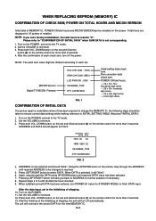
... and MICON VERSIONcan be changed is reached.
5. Turn on the POWER, and set to finish DATA input. MICON Version Digital TV MICON Fimware
HCS CHK SUM : 07EA HRM CHK SUM : 9BD4 LCD PWR ON : 0000 OEC6088A_T039 DTV CA03B72232
FIG. 1
Initial setting data check sum. Turn on the POWER, and set and Channel...
Service Manual - Page 16

...BAK LIGHT CENT 24 BAK LIGHT MAX 25 BAK LIGHT MIN 26 BRIGHT CENT 27 BRIGHT MAX 28 BRIGHT MIN 29 TINT ... 6. Using the remote control, set to select "CONTRAST MAX". 4. Playback the DVD(480i) disc. (HDMI Input) 18.
Before applying new silicon grease, remove all... becomes "150" 5. Press the INPUT button on the remote control for TV, VIDEO1, VIDEO2, ColorStream HD, HDMI-0 and PC mode, press the ...
Service Manual - Page 19

... B DRIVEʢWʣ 20 B CUTOFFʢWʣ 21 H POSI 60
22 V POSI 60
23 BAK LIGHT CENT
24 BAK LIGHT MAX
25 BAK LIGHT MIN
26 BRIGHT CENT
27 BRIGHT MAX
28 BRIGHT MIN
29 TINT
30 SHARP CENTER
31 SHARP MAX
32 SHARP MIN
33 CONT CENTER
34 CONT MAX...
Service Manual - Page 21
No
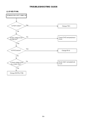
No Is there voltage at pin 1 No of IC401 19V? Change F401. Check IC401 and peripheral circuit.
Yes
Change DIGITAL PCB. Change R412. E-1 TROUBLESHOOTING GUIDE
(LCD SECTION)
POWER DOES NOT TUNER ON
Is F401 broken? Yes
No
Is there voltage at pin 10 of IC402 6V? Yes
Yes Is R412 broken?
Check IC402 and peripheral circuit.
Service Manual - Page 22

TROUBLESHOOTING GUIDE
THE PICTURE APPEARS, BUT THE AUDIO DOES NOT
APPEARS. (ATRFMODE)
No Is CP1001 connected?
No
Is there signal at pins
Yes
28 and 30 of TU2801? No
Yes Is there ... at pins 2 Yes and 5 of IC1001? Check IC1002 and peripheral circuit. Check IC701 and peripheral circuit.
Connect CP1001. No
Change TU2801.
No
Is there signal at pins
Yes
1 and 4 of IC1002?
Service Manual - Page 23

Check Q3410 and peripheral circuit.
Check IC401, T401, D437 and peripheral circuit. E-3 Yes
No Is CD7201 connected? Is there voltage at pin No 28,29,30 and 31 of CP2407 5V? Change IC2405. Yes
Is there ...at pins 7, Yes 8, 10, 11, 13, 14, 16, 17, 19 and 20 of CP406
Yes
Connected CD7201. Change V2301(PANEL). TROUBLESHOOTING GUIDE
THE PICTURE DOES NOT APPEAR (1)
No Does backlight shine?
Service Manual - Page 26
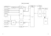
...AV2 CVBS
IN
J702
RCA-349-00C-02 AV2 AUDIO L/R
S+COAXIAL J706
R102-D04KAF-06
S1 Y
IN
S
S1 C
OUT
COAXIAL
USA STEREO IC901 AN5832SA-E1V
Analog Tuner AUDIO L/R
AUDIO SW L/R IC704, 705
MM1501XNRE
PC/HDMI/RF SW AUDIO L/R
SW AUDIO L/R 1
AV ...
AN17808B
AMP L/R
SPEAKER L/R SP1001, SP1002
S0412F03
LVDS IC IC2405 ICSV385AGLFT
Tx OUT
CP2407 20389-Y30E
LCD PANEL V2301
LK255T3LZ5AZ
F-1
F-2
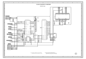
Service Manual - Page 27

...CP3401
1 SOUND +B 2
3 4
SOUND GND
5
6
GND
7
8 SW +12V 9
10 LCD+B
11 POWR_ON_H
12 LIGHTE_CTL
13 INVERTER_H
14
AT +5V
15
16 POWER FAIL
17
18
GND
19
...SW +1.5V 23
REG+9V IC3404 P.CON +9V BA00BC0WFP
SOUND AMP IC1001
AN17808B
AV SW IC701 AN15853B-E1
Q3410 LCD +B RSQ035P03
PANEL V2301 LK255T3LZ5A
Q3406 P.CON +5V 2SB1132
AD CONVERTER IC6601
MST3583M-LF-110
SUBɹMICON IC101
...
Service Manual - Page 35
... NFIO1 NFIO0
C2503 0.1 B
7
48 47 46 45 44 43 42 41 40 39 38 37 36 35 34 33 32 31 30 29 28 27 26 25
HY27US08281A-TP
FLASH MEMORY IC
FOR FIRM UPDATE
CP2401 YKF45-0036N
1
+5V
2
USBN
3
USBP
6
4
GND
JG2412 JG2413 JG2414
R2422 15K R2423 15K
FROM/TO...
Service Manual - Page 39
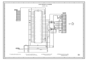
...220
V-S
B2502 FCM1608KF-151T06
R2507 180
B2503
FCM1608KF-151T06
B2504
FCM1608KF-151T06
CD7201 CHRU1301
LCD PANEL
V2301 LK255T3LZ5AZ
C2595 6.3V 220 V-S
NOTE:THE DC VOLTAGE AT EACH PART ...G
LVDS SHEMATIC DIAGRAM
(DIGITAL PCB)
C2591 0.1 B
C2593 0.1 B C2592 6.3V 220
V-S
C2594 0.1 B
3.3 Vcc
1
28 27 26 25 24 23 22 21 20 19 18 17 16 15 14 13 12 11 10 9
R7
2
3.3 TxIN5
R5
3
3.3 TxIN6
...
Service Manual - Page 41
...TO FLASH
TX_[X242]
RX_[X242]
FROM/TO FRONT END AFT_1 AFT_2 SD-H AFT
5
FROM/TO POWER3
DTV_ON-H LIGHT_CTL
LCD-H INVETER_H POWER_ON-H POWER_FAIL
P.CON+5V
4
FROM/TO SOUND
POWER_ON_MUTE_H
5.0 LCD_ON
5.0 LCD_H
5.0 NC NC
0 NC NC...NC
0 REMOCON_IN
5.0
LED-H DTV_ON-H POWER_ON-H
C102 0.01 B
R104
100
33 32 31 30 29 28 27 26 25 24 23
44 43 42 41 40 39 38 37 36 35 34
5.0
VAREF
NC
NC
0
5.0
...
Service Manual - Page 42

...C908 2.7 0.1 B C909 2.7 0.033 B C901 2.2 2.2 B
0 NC
16 15 14 13 12 11 10 9
8
7
6
5
4
3
2
1
USA STEREO IC IC901 AN5832SA-E1V
NC
L-R RBF
2.2
WB TIME
0 NC NC
WB DET
LOUT 2.2
SPE TIME
ROUT 2.2
SPE DEL
AGC DET
1.7
C916 2.2 B
TU_AUDIO_L C919 1B...KTA1504S_Y_RTK 0
R718 470 R742 470
C725 1B 36 35 34 33 32 31 30 29 28 27 26 25 24 23 22 21 20 19
C721
0.01 B C722
0.01 B C723
0.01 B C724...
Service Manual - Page 46

... 100 ZL_P
5.6K 1/2W
R426
C422_1
VCC REGULATOR Q405 KTC3209_Y
19.0
34.8
19.4 R424 47K
0 0.8
0 VCC REGULATOR Q406
KTC3875S_Y_RTK
15K
R427
CAUTION: IS THE LIVE CONNECTION
HS405 763WAA0365
IC408 PS2561AL1-1-V(W)
2.5
0
IC409 PS2561AL1-1-V(W)
0.8
0
C468 250V0.001 KX
C427 250V 470P KX
C463 250V470P KX
34 21
34 21
R435 1K
GND
NC...
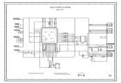
Service Manual - Page 49

...GND
7
7
GND
GND
7
SW+12V 8
8
SW+12V
GND
8
7
SW+12V 9
9
SW+12V
GND
9
LCD+B
10
10
LCD+B
GND
10
POWER_ON_H 11
11 POWER_ON_H
Analog/Dimming 11
LIGHTE_CTL 12
12 LIGHTE_CTL
ON/OFF
12
INVETER_H 13
13 INVETER_H
PWM/Dimming ... LA NOMENCLATURE DES PIECES
C
D
TO LCD PANEL CD7201
LCD PANEL V2301
E
21
GND
22
NC
23
GND
24
GND
25
GND
26
GND
27
GND
28 VDD+5V
29 ...
Similar Questions


Screws That Connect Tv Stand
What size are the four screws that connect the stand to the back of this tv? I need to replace them.
What size are the four screws that connect the stand to the back of this tv? I need to replace them.
(Posted by jdjdot5 11 years ago)

Sharp 27n-s100 Tv
is there a way to turn on a Sharp 27n-S100 TV without using the power button (non existant) or the r...
is there a way to turn on a Sharp 27n-S100 TV without using the power button (non existant) or the r...
(Posted by susannaelliott 11 years ago)


My Sharp Lc-26sh12u Will Not Work Through My Stero System On Channel 60.
I have hooked up my sharp T.v. to my Philips stero system through both the digital input and regular...
I have hooked up my sharp T.v. to my Philips stero system through both the digital input and regular...
(Posted by sailrv88 13 years ago)