LiftMaster MT Support Question
LiftMaster MT Support Question
Find answers below for this question about LiftMaster MT.Need a LiftMaster MT manual? We have 2 online manuals for this item!
Question posted by crusin31again on May 21st, 2014
How Big Of A Garage Door Will A Model Mt 1211 Lift Weight And Width ?
I have a 13' wide 8' high door. Its a older heavy door. I have a new model MT 1211 I had for a 9' wide 12' high door that I decided not to use. So with springs adjusted properly will this work on the larger door ?
Current Answers
Related LiftMaster MT Manual Pages
MT5011E Installation Manual - Page 1
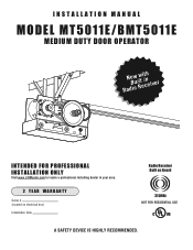
INSTALLATION MANUAL
MODEL MT5011E/BMT5011E
MEDIUM DUTY DOOR OPERATOR
RaNdoBiwuoiRlwteiitcnheiver
INTENDED FOR PROFESSIONAL INSTALLATION ONLY
Visit www.LiftMaster.com to locate a professional installing dealer in your area.
2 YEAR WARRANTY
Serial # (located on electrical box)
Installation Date
Radio Receiver Built on Board
315MHz
NOT FOR RESIDENTIAL USE
A SAFETY DEVICE IS HIGHLY RECOMMENDED.
MT5011E Installation Manual - Page 4
...
SAFETY
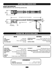
DISCONNECT Quick disconnect door arm for emergency manual door operation. BRAKE (BMT ONLY Solenoid actuated disc brake LIMIT ADJUST:. . . . . .Fully adjustable up to + 50˚C)
4 lbs/ sec. OPERATOR DIMENSIONS
WEIGHTS AND DIMENSIONS
HANGING WEIGHT:80-110 LBS. (36.29-49.9 kg) (Including Track)
12-1/2" (31.75 cm)
9-1/2" (24.13 cm)
16-3/16" (41.12 cm)
Door Height Plus 4 feet...
MT5011E Installation Manual - Page 5
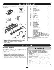
... components were provided.
15 1
14
^
^OPEN
CLOSE
O
STOP
8
4
10 9
7
2 12
3
13 11
6 5
ITEM DESCRIPTION
QTY
1
Operator
1
2
Track (left & right)
Door height plus 2'
2
3
Track Spacers
2
...
NOTE: Depending on door height, the quantity of track spacers and hardware may not reverse when required.
• NEVER try to loosen, move or adjust doors, door springs, cables, pulleys, ...
MT5011E Installation Manual - Page 6
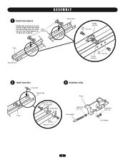
For doors up to 12' use 2 track spacers, for 14' doors use 3 spacers.
ASSEMBLY
1 Install track spacers
Position the track spacers evenly over the length of the track using the pre-punched holes. Track Spacers
Header End
Flange Hex Nut
Bolt 3/8" - 16 x 3/4"
Track Operator End
Bolt 3/8" - 16 x 3/4"
Flange Hex Nut
2 Install front idler
Front ...
MT5011E Installation Manual - Page 9

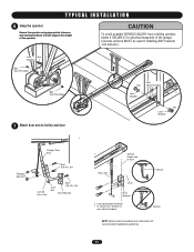
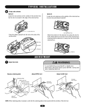
... up to interfering structures or location of the door. TYPICAL INSTALLATION
DETERMINE HEADER BRACKET MOUNTING LOCATION
The trolley operator is generally mounted over the center of Door Travel
9 However, off center on to the header wall and the ceiling.
Extend the line on torsion spring doors. Extension springs require center mounting.
1 Mark the center of...
MT5011E Installation Manual - Page 10

... or DEATH: • Header bracket MUST be used if mounting header bracket or 2x4 into masonry. • NEVER try to loosen, move or adjust door, springs, cables, pulleys, brackets, or their hardware, ALL of which are under EXTREME tension. • ALWAYS call a trained door systems technician if door
binds, sticks, Aor iVs oEut Rof bTalaInSceS.
EMENT...
MT5011E Installation Manual - Page 11
... and locking hardware that will support the weight of Door
PRECAUCIÓNVertical
Door
Door Bracket
Use appropriate hardware to secure door bracket to door (Not Provided). Vertical
NOTE: Refer to structural supports of the garage. Lock
Nut
Washer
Bolt (Not Provided)
Bolt (Not Provided)
7 Attach door arm to trolley and door
AVERTISSEMENT
Bolt
Nut
(Not Provided)
ATTENTION Lock...
MT5011E Installation Manual - Page 12
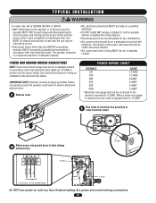
...the operator power switch.
When a larger wire gauge is 12 AWG. Operator MUST be properly grounded and connected in accordance with local electrical codes. Must use 14 AWG or heavier wire for wiring... codes
NCIA
ADVERTENCIA
ÓN
ADVERTENCIA
10
Attach power and ground wires to high voltage terminal strip
Power
Conduit
Ground Neutral Hot
Control Line Power 115 Vac ...
MT5011E Installation Manual - Page 13
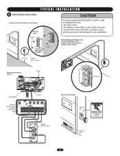
... recommended for 3-button control station
Remove cover
^OPEN Screws
CLOSE
O
STOP
Wall
Secure using appropriate hardware
5' (1.5 m)
3-Button Control Station
CAUTION
To prevent possible SEVERE INJURY or DEATH, install reversing sensors when: • The radio is used. • The 3-button control station is out of sight of the door. • Or ANY other control (automatic...
MT5011E Installation Manual - Page 14
...plate
Adjust OPEN limit
Retaining Plate OPEN Limit Nut OPEN Limit Switch CLOSE Limit Nut
AVERTISSEMENCLTOSE Limit Switch
ATTENTION
Increase Door Travel
Adjust CLOSE limit
Increase Door Travel Decrease Door Travel
AVERTISSEMENT
AVERTISSEMENT Decrease Door Travel...the electrical box. TYPICAL INSTALLATION
12 Setup radio antenna
Option A Locate the wire antenna on the outside of the electrical ...
MT5011E Installation Manual - Page 15
...SAFETY DEVICES
PHOTO EYES When properly connected and aligned, the photo eye will detect an obstruction in the path of cotterpin to the full open position.
Remove Tape Holding Cotter...of the door.
ADJUSTMENT
2 Adjust the clutch
• Apply power to operator • Turn clutch nut to release tension. • Re-tighten nut until there is just enough
tension to Spring
Insert Cotterpin...
MT5011E Installation Manual - Page 17
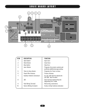
... Antenna Auxiliary Antenna Connection
LED
Field Wiring Terminal Factory Wiring Connector
FUNCTION Open Door Close Door Stop Door Programs the remote controls and performs additional programming Programs the Timer to Close Primary Antenna For use with external antenna kit EXT-ANT. Not Provided Used during programming and diagnosing error codes Field wiring connections Factory wiring harness...
MT5011E Installation Manual - Page 18
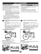
... the Monitored Safety Device is used . • The 3-button control station is out of sight of the door. • Or ANY other control (automatic or manual) is removed, the operator will go into a Restricted Close mode**. The operator will stop with constant pressure to close.
• Open override that reverses when closing by...
MT5011E Installation Manual - Page 20

... Timer to close from 5 to Comply with door in fully closed position. 2. MODE
B2 B2 with FCC and or Industry Canada (IC) rules, adjustment or modifications of the next open command. Press and release the LEARN button (... controls will light). 3.
Begin with FCC Standards FOR HOME OR OFFICE USE. Press and release the LEARN button (LED will be erased.
Press and hold the desired button of...
MT5011E Installation Manual - Page 21

... limits. If the limits are not set properly, remove power and adjust
limits (refer to make sure they are working properly.
Test all safety instructions included in a safe manner and how to the Adjustment section for operation of the photo eyes or sensing
edge. 3. Press OPEN button. (The door should continue closing if in the path of...
MT5011E Installation Manual - Page 22
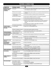
DOOR OPENS/CLOSES TOO FAR
DOOR REVERSES UNEXPECTEDLY
TTC NOT FUNCTIONING
B) Clutch slipping C) Brake not functioning properly
Limits not adjusted properly
Intermittent Safety Device activation A) Monitored Safety Devices
➤ Adjust clutch, see ADJUSTMENT section. ➤ Check brake mechanism to close by holding the CLOSE button for assistance. ➤ Adjust clutch, see ...
MT5011E Installation Manual - Page 23
...the capacitor. Replace Logic Board.
Door height or speed may exceed ...OPEN
OPEN CLOSE STOP
Remove Jumper to the operator. (Not a logic board failure.)
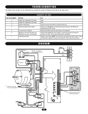
DIAGRAM
Brake (BMT only)
Blue*
Blue*
* If brake is not supplied,
wires are capped separately
Green
Black Black
L2 L1
Capacitor
Yellow Red Yellow
Red
Motor
** If interlock is not used,
wires are capped together. Check clutch adjustment...
MT5011E Installation Manual - Page 28
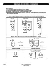
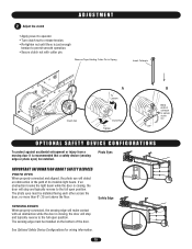
...SAFETY DEVICE CONFIGURATION section.
12
Open Close
Open Close
C2 MODE ONLY
See note 2. If a STOP button is not used , a jumper must be...proper installation and operation
with the Commercial Door Operator.
3 BUTTON STATION OR 3 POSITION KEYSWITCH WITH SPRING RETURN TO CENTER AND STOP BUTTON
STANDARD 7635
2 OR MORE 7635
KEY LOCKOUT 7635
Open Close Stop
Open Close Stop
Open Close Stop
Open...
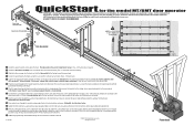
MT5011E QuickStart Guide Manual - Page 1
... the operator to close the door after a preset time, adjustable from 5 to ensure that timer is safe for its intended use 3 of timer setting. Requires...OPEN
TTC
LEARN STOP CLOSE OPEN LEDD14
1
2
3
4
5
6
7
3-BUTTON REMOTE CONTROL TO OPERATE AS A WIRELESS 3-BUTTON CONTROL STATION NOTE: The feature will light). 2. TO PROGRAM 1. Press and hold the TTC button for the model MT/BMT door...
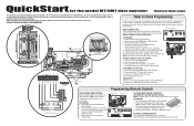
MT5011E QuickStart Guide Manual - Page 2
... codes.
11 Adjust the limit switches to the front wall. Reinstall cotter pin when finished.
13 Additional programming and troubleshooting can pivot. Follow ALL local electrical codes.
10 Run control wires through the power wiring conduit hole in the electrical box enclosure. BHreaacdke6ert
2
1st
2nd
5
QuickStart for the model MT/BMT door operator
IMPORTANT: This...
Similar Questions

My Lift Master Mt-1211, 1/2 Hp
Will open from closed position but will not close when opened.Tried both remote and wall control. th...
Will open from closed position but will not close when opened.Tried both remote and wall control. th...
(Posted by patrickkaren86 6 years ago)


My Liftmaster Mt-1211 Will Not Close.
My Mt 1211 will not close. When I pres the close button the system will move approximately one foot,...
My Mt 1211 will not close. When I pres the close button the system will move approximately one foot,...
(Posted by grindle1302 10 years ago)


Install A
Cps-u Model Mt 5011
install a cps-u to a model MT 5011 wiring to motor head.
install a cps-u to a model MT 5011 wiring to motor head.
(Posted by Anonymous-58243 12 years ago)