Icom IC-7000 Support Question
Icom IC-7000 Support Question
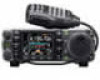
Find answers below for this question about Icom IC-7000.Need a Icom IC-7000 manual? We have 2 online manuals for this item!
Question posted by ALBEPRIETO on October 2nd, 2014
Frontpanalelectronic Conection
The Lights Of Front And Radio Flick For Moment And My Mechanic Changes The Altenator And Not Afect.please Telwhat Is Wrong Thanks
Current Answers
Related Icom IC-7000 Manual Pages
Instruction Manual - Page 2
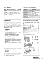
... MANUAL CAREFULLY before attempting to thank you for making the IC-7000 your radio of choice, and hope you have a choice of many different radios in the internal circuit and
...IC-7000. SAVE THIS INSTRUCTION MANUAL. EXPLICITDEFINITIONS
WORD
DEFINITION
R DANGER!
NOTE
Recommended for the IC-7000. Personal injur y, fire hazard electric shock may occur. We want to take a couple of moments...
Instruction Manual - Page 5
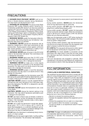
...WARNING! NEVER operate or touch the transceiver with the IC-7000 ONLY. This may result in an electric shock or...IC-7000 may result in a residential installation. cian for advice.
CAUTION: Changes or modifications to the transceiver by one or more than the linear amplifier's maximum input level, otherwise, the linear amplifier will damage the transceiver's surfaces. This device emits Radio...
Instruction Manual - Page 19
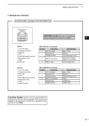
... HM-103 is connected
PIN NO. This could cause damage to indicate HM-151 is designed for use the supplied HM-151
(microphone) with the IC-7000 ONLY.
10 D Microphone connector MICROPHONE CONNECTOR INFORMATION
1 PANEL DESCRIPTION
Rear panel view
87654321
CAUTION: DO NOT short pin 1 to ground as
this can damage the...
Instruction Manual - Page 24
...1-2 mm 1⁄16 in)
ANTENNA SWR
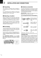
Each antenna is recommended when transmitting. The IC-7000 has an SWR meter to the delivering carrier or dealer. Make the distance between the...9632; Antenna connection
For radio communications the antenna is higher than approx. 2.0 : 1, the transceiver's power drops to one of accessory equipment included with the IC-7000, see description on p.
...
Instruction Manual - Page 28
... supply
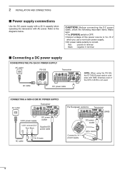
CONNECTING THE PS-126 DC POWER SUPPLY
AC outlet
PS-126
Transceiver
AC cable
DC power cable
NOTE: When using the PS-126, the IC-7000 Europe version complies with AC power. at least 22 A
Red Black +_
Supplied DC power cable
AC cable
30 A fuses
For European versions
Transceiver [GND]
DC...
Instruction Manual - Page 29
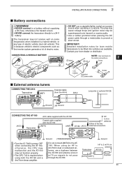
...'s electric components such as a power source when operating in a hybrid vehicle, or any type of the two external connectors
Ground [TRANSCEIVER]
Ground
• Turn the IC-7000's power OFF when connecting the AT-180, otherwise, the CPU may malfunction and the AT-180 may be fitted into vehicles are available. When using...
Instruction Manual - Page 30
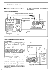
... settings could cause a fire or damage the linear amplifier.
The IC-7000 SEND line (ACC connector pin 3) is compatible with the IC-PW1/EURO)
ANT1
Ground
CONNECTING A NON-ICOM LINEAR AMPLIFIER
R WARNING...: 100-120/200-240 V
European version
: 230 V
Transceiver
Coaxial cable
(supplied with the IC-7000, before operation.
21
To an antenna
RF OUTPUT
RF INPUT ALC
SEND
50 Ω coaxial...
Instruction Manual - Page 35
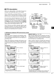
... memory mode, the lastused frequency and operating mode for split frequency operation.
Changed frequency (14.123 MHz) does not appear and memorized frequency (14.100 MHz) appears instead.
26 The IC-7000 has two VFOs, specially suited for that VFO appear.
The IC-7000 VFO is selected again. MEMORY MODE (pp. 100-108) Each memory...
Instruction Manual - Page 43
...RTTY
CW-R RTTY-R
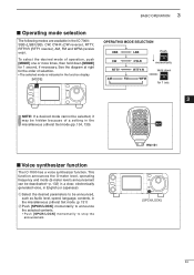
momentarily Hold down [MODE] for the order of a setting in the IC-7000: SSB (LSB/USB), CW, CW-R (CW reverse), RTTY, RTTY-R (RTTY reverse), ...9
GENE
� 50
144 430 F-INP
0
CE ENT
MODE
HM-151
3
■ Voice synthesizer function
The IC-7000 has a voice synthesizer function.
q S elect the desired parameters to stop the announcement.
[SPCH/LOCK]
34
This ...
Instruction Manual - Page 54
4 RECEIVE AND TRANSMIT
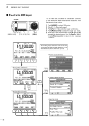
■ Electronic CW keyer
[MODE]
[F-1]
[MENU/GRP]
[F-2] [F-3] [F-4]
[DIAL]
The IC-7000 has a number of the multi-function keys ([F-1] to [F-4])
to select the desired menu. q Push [MODE] to enter the keyer send menu.
w Select S-1. (See right page.) e ...
Instruction Manual - Page 78
...grp)] also to turn OFF.
[Y]
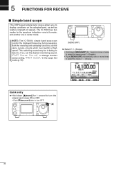
69 If so, set the desired monitoring sound, "FAST Sweep Sound," or change the fast sweep setting, "FAST Sweep," in the scope Set mode (p. 72).
[MENU/GRP]
➥ ...(Graphic). • Push [MENU/GRP] momentarily one is center mode. N OTE: The IC-7000's simple band scope can monitor the displayed frequency during sweeping. 5 FUNCTIONS FOR RECEIVE
■ ...
Instruction Manual - Page 94
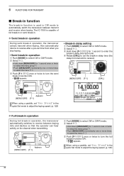
.../GRP] for 1 second once or twice to select the menu group M.
• Push [MENU/GRP] momentarily one or more times to select the menu M-3. The IC-7000 is used in CW mode to select CW or CW-R mode.
r Rotate [DIAL] to set the break-in delay time (the
delay from transmit to...
Instruction Manual - Page 96
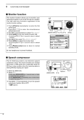
... Level." w Select M-3.
• Hold down [F-4 DEF] for 1 second to return to enter the Set mode menu. t Push [F-2 ≥] to prevent feedback.
■ Speech compressor
The IC-7000 has a built-in, low distortion speech compressor circuit.
q Push [AF(set)] momentarily to default condition.
r Rotate [DIAL] to turn the speech compressor function ON or...
Instruction Manual - Page 101
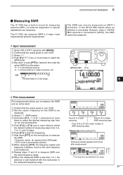
... entire band. e Select G-3 (SWR meter). 6 FUNCTIONS FOR TRANSMIT
■ Measuring SWR
The IC-7000 has a built-in circuit for the SWR to be
measured.
However, when a 144/430 MHz .... y Push [F-1] to start the measuring. Push [F-1] to start mesuring. The IC-7000 can measure SWR in 2 ways-spot measurement and plot measurement.
The SWR can only be measured on the microphone to...
Instruction Manual - Page 113
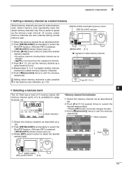
.... • All memory channels including blank channels can be
selected. • [Y]/[Z] on the microphone also changes the channels.
BNK
Push
[MENU/GRP] [RIT] (outer) control [F-4]
104 y Push [Z(menu/grp)]...the memory scan indication. (p. 113)
Push [F-1 SEL]
8
D Selecting a memory bank
The IC-7000 has a total of 5 memory banks (99 memory channel each), A to speed up the memory...
Instruction Manual - Page 123
... is different for 1 second
again to the connected antenna automatically. See page 130 for each time you change the frequency. However, operation is emitted, and "
"
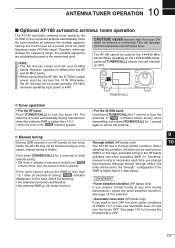
indicator blinks; When operating on " and turn...CALL] for the HF and 50 MHz bands.
• When connecting the AT-180, the IC-7000's output power must be set to the "through" configuration if the
If the tuner cannot reduce...
Instruction Manual - Page 124
... S-2 or S-3
Either Y or Z
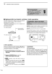
■ Optional AH-4 automatic antenna tuner operation
The AH-4 matches the IC-7000 to a long wire antenna more than 7 m/23 ft long (3.5 MHz and above). • See page ...PTT is pushed after the frequency is connected to re-tune the antenna before transmitting when you change the frequency-even slightly. NEVER operate the AH-4 when it is required for 1 second.
...
Instruction Manual - Page 125
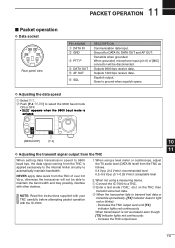
...): acceptable level
2. When not using a measuring device. Goes to a TNC. q Connect the IC-7000 to ground when squelch opens. e W hen the transceiver fails to automatically maintain bandwidth. r DATA ...doesn't light red or blinks): - Decrease the TNC output level until [TX]
indicator lights red continuously. When transmission is not successful even though [TX] indicator lights red ...
Instruction Manual - Page 145
... 01h to 7Fh.
70h
Address of 70h (default)
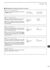
50 CI-V Transceive
Transceive operation is automatically set according to 100% range in hexadecimal code.
on the IC-7000 automatically changes those of 7Fh
OFF Transceive OFF
13
136 ■ Miscellaneous (others) Set mode (continued)
47 Front Keypad Type
This item selects the keypad type...
Instruction Manual - Page 162
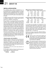
... recommended for different frequencies, a relative table shows a guideline for long periods of the IC-7000 which display the "CE" symbol on the transmitter being activated for long periods. (actual...cases from the RF power at http://www.arrl.org/.
• Typical amateur radio installation Exposure distance assumes that the predominant radiation pattern is forwards and that show precalculated...
Similar Questions

How Can I Open The Ic 7200 For Transmission On Marine Channels?
I have been adviced that it is possible to modify so that I for safety reasons only, can trx on mari...
I have been adviced that it is possible to modify so that I for safety reasons only, can trx on mari...
(Posted by Runeedamm 5 months ago)

Icom Ic7000
I have a Icom ic7000 with serial numer 3001367 ;Can you give me the year of construction please ?tha...
I have a Icom ic7000 with serial numer 3001367 ;Can you give me the year of construction please ?tha...
(Posted by noelvdb1 1 year ago)


I Need The Removable Display Unit. Is That Possible?
I do not have the plug in display/control unit for my icon 7000. I would like to purchase a new or w...
I do not have the plug in display/control unit for my icon 7000. I would like to purchase a new or w...
(Posted by wa8sie 2 years ago)

Icom Ic-7000 Serial Numbers
Does the serial number indicate year of manufacture on the Icom IC-7000?
Does the serial number indicate year of manufacture on the Icom IC-7000?
(Posted by Anonymous-163051 6 years ago)