Hunter 40120 Support Question
Hunter 40120 Support Question
Find answers below for this question about Hunter 40120.Need a Hunter 40120 manual? We have 3 online manuals for this item!
Question posted by rledbetter0210 on January 11th, 2022
Wiring Diagram For Model40120
The person who posted this question about this Hunter product did not include a detailed explanation. Please use the "Request More Information" button to the right if more details would help you to answer this question.
Current Answers
Answer #1: Posted by SonuKumar on January 12th, 2022 8:10 AM
SonuKumar

Member since:
May 9th, 2021 Points: 16,609,800

Member since:
May 9th, 2021 Points: 16,609,800
Please respond to my effort to provide you with the best possible solution by using the "Acceptable Solution" and/or the "Helpful" buttons when the answer has proven to be helpful.
Regards,
Sonu
Your search handyman for all e-support needs!!
Related Hunter 40120 Manual Pages
Owner's Manual - Page 1
Electronic/Mechanical Thermostat
installation and operation manual
Model 40120
1
44018-01 04-01-2008
Owner's Manual - Page 2
they may be reached toll-free at 1-888-830-1326.
2 For assistance with wiring or operation, our Technical Support Group is available from 8 am to 5 pm CST.
Owner's Manual - Page 3
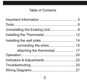
Table of Contents
Important Information 5 Tools 6 Uninstalling the Existing Unit 9 Installing the Thermostat 12 Installing the wall plate 14
connecting the wires 15 attaching the thermostat 17 Operation 20 Indicators & Adjustments 22 Troubleshooting 25 Wiring Diagrams 27
3
Owner's Manual - Page 4
Please read this manual before beginning installation and save this booklet for choosing a Hunter thermostat. Thank you for complete operation instructions.
4
Your new Hunter thermostat will provide years of reliable service and year-round energy savings.
Electronic/Mechanical Thermostat
Model 40120
Congratulations!
Owner's Manual - Page 5
....
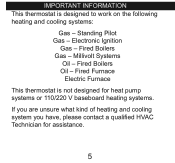
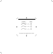
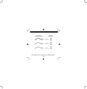
If you are unsure what kind of heating and cooling system you have, please contact a qualified HVAC Technician for assistance.
5 Fired Furnace
Electric Furnace
This thermostat is designed to work on the following heating and cooling systems:
Gas - Electronic Ignition
Gas - Millivolt Systems
Oil - Standing Pilot Gas - Fired Boilers Gas - Fired...
Owner's Manual - Page 6
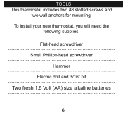
To install your new thermostat, you will need the following supplies:
Flat-head screwdriver
Small Phillips-head screwdriver
Hammer
Electric drill and 3/16" bit
Two fresh 1.5 Volt (AA) size alkaline batteries
6 Tools This thermostat includes two #8 slotted screws and
two wall anchors for mounting.
Owner's Manual - Page 7
The wires must be labeled prior to removal to ensure proper reconnection.
7 NOTICE! Do not disconnect the wires from the existing thermostat before reading these instructions.
Owner's Manual - Page 9
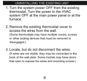
Remove the existing thermostat cover to access the wires from the existing
thermostat. Locate, but do not disconnect the wires.
(If wires are not visible, they may have multiple covers, screws or other locking devices that open to expose the wires and mounting screws.)
9 Turn the power to the back of the wall plate. Some models may...
Owner's Manual - Page 10
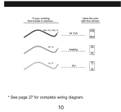
If your existing thermostat is marked... RH / r / vr / 4 w / h g / f
label the wire with this sticker:
24 Volt RH
heating W
fan G
G W RH
* See page 27 for complete wiring diagram.
10
Owner's Manual - Page 11
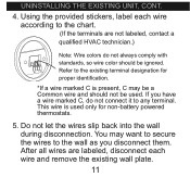
... terminals are labeled, disconnect each wire and remove the existing wall plate.
11 After all wires are not labeled, contact a
qualified HVAC technician.)
W RH G W
Note: Wire colors do not connect it to the existing terminal designation for non-battery powered thermostats.
5. Refer to any terminal. You may be a Common wire and should be used. uninstalling...
Owner's Manual - Page 12
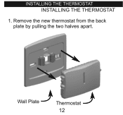
installing the thermostat INSTALLING THE THERMOSTAT
1.
Wall Plate
Thermostat 12 Remove the new thermostat from the back plate by pulling the two halves apart.
Owner's Manual - Page 14
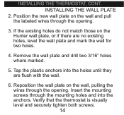
... the wall plate and mark the wall for two holes.
4. installing the thermostat, cont. Remove the wall plate and drill two 3/16" holes where marked.
5. If the existing holes do not match those on the wall, pulling the wires through the opening . Reposition the wall plate on the Hunter wall plate, or...
Owner's Manual - Page 16
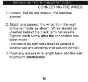
CONNECTING THE WIRES
1. installing the thermostat, cont. Wires should be inserted behind the black terminal shields. Push any extra wires should be wrapped in electrical tape and carefully pushed back into the wall to the terminals as shown. Loosen, but do not remove, the terminal screws.
2. Match and connect the wires from the wall to prevent...
Owner's Manual - Page 18
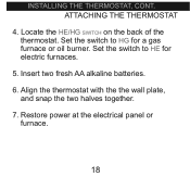
... on the back of the thermostat. Insert two fresh AA alkaline batteries. 6. Align the thermostat with the the wall plate,
and snap the two halves together. 7. ATTACHING THE THERMOSTAT
4. Restore power at the electrical panel or
furnace.
18 Set the switch to HG for electric furnaces.
5. installing the thermostat, cont. Set the switch to...
Owner's Manual - Page 21
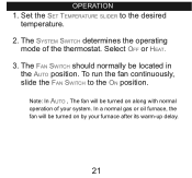
... Fan Switch should normally be turned on by your system. Note: In Auto , The fan will be turned on along with normal
operation of the thermostat. In a normal gas or oil furnace, the fan will be located in
the Auto position.
To run the fan continuously, slide the Fan Switch to...
Owner's Manual - Page 27
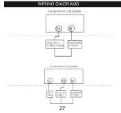
wiring diagrams
2-w ire HeatOnlySystem
Rh W
Heat24V or
HeatRelay
M illivoltSupply orValve
3-w ire HeatOnlySystem
G Rh W
Fan
Heat24V
Relay Supply
HeatRelay orValve
27
Owner's Manual - Page 10
RH / r / vr / 4 w / h g / f
label the wire with this sticker:
24 Volt RH
heating W
fan G
G W RH
* Vea la página 27 para el digrama eléctrico completo
10 If your existing thermostat is marked...
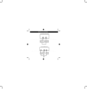
Owner's Manual - Page 27

wiring diagrams
2-wire Heat Only System
Rh W
Heat 24V or
Heat Relay
Millivolt Supply or Valve
3-wire Heat Only System
G Rh W
Fan
Heat 24V
Relay Supply
Heat Relay or Valve
27
Owner's Manual - Page 10
If your existing thermostat is marked... RH / r / vr / 4 w / h g / f
label the wire with this sticker:
24 Volt RH
heating W
fan G
G W RH
* Voir la page 27 pour le diagramme de câblage complet
10
Owner's Manual - Page 27
wiring diagrams
2-wire Heat Only System
Rh W
Heat 24V or
Heat Relay
Millivolt Supply or Valve
3-wire Heat Only System
G Rh W
Fan
Heat 24V
Relay Supply
Heat Relay or Valve
27
Similar Questions

What Makes The Model 40120 Thermostat Quick Before It Starts The Heating System?
(Posted by jjanders125 3 years ago)

Hunter Wiring Diagram For Mod.44860
The heat mode will not go on. Please send proper wiring diagram.
The heat mode will not go on. Please send proper wiring diagram.
(Posted by danmaria133 10 years ago)

How To Install With 2 Wires Only
i have gas/electric furnace. but only have a 2 wire hook up on my old thermostat. i have heat only. ...
i have gas/electric furnace. but only have a 2 wire hook up on my old thermostat. i have heat only. ...
(Posted by plittledeb 11 years ago)

Do You Have A Wiring Diagram For The Hunter Thermostat Modle 44132
(Posted by STEVEDENISE 11 years ago)

40120 Thermostat Cuts Off After 20 Seconds While Heating.
(Posted by RenaldoWarren 11 years ago)