Honeywell TB6575B1000/U Support Question
Honeywell TB6575B1000/U Support Question
Find answers below for this question about Honeywell TB6575B1000/U - SuitePro Digital Fan Coil Stat.Need a Honeywell TB6575B1000/U manual? We have 1 online manual for this item!
Question posted by apetric2 on August 7th, 2013
Thermostats
I'm trying to install my new thermostats- TB6575B1000. I have a line voltastays stem. 2 pipes 120 volts. I can't figure out how to properly install the wires, though there are just two
Current Answers
Related Honeywell TB6575B1000/U Manual Pages
Installation Instructions - Page 1
... via Setup button on thermostat.
• Displayable pipe sensor temperature readout to aid in output wiring and external links between wiring terminals allow the fan motor to always begin on heat when needed.
• Economy Setback options via dry contact or Activity Sensing
• Advanced fan control with a press of Digital Fan Coil thermostats for multiple applications.
All...
Installation Instructions - Page 2
...only): TR21-A • PS20 -
mm) wires. The TB6575A1000 model is not field replaceable....
Yes
Yes
Yes Yes
4
5
Pipe Sensorb
Yes
62-0311-05
2
...120°F). box or vertical 2 x 4 in .
NOTES: 1.
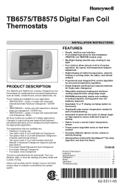
Electrical Ratings. Dimensions: See Fig. 1 on page 3. TB6575/TB8575 DIGITAL FAN COIL THERMOSTATS
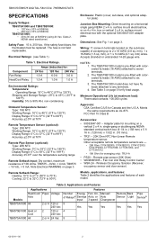
SPECIFICATIONS
Supply Voltages:
TB6575A1000 and TB6575B1000: • 120...
Installation Instructions - Page 3
... is not a safety device. TB6575/TB8575 DIGITAL FAN COIL THERMOSTATS
a The five relays are line voltage powered devices. Hot or cold air from the sun or appliances.
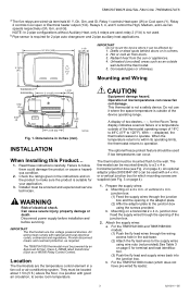
4. Failure to 120°F). Attach the supply wires: a. Location
The thermostats are supplied (see Fig. 2 on page 4).
1. INSTALLATION
When Installing this Product...
1. Installer must comply with a 4 x 4 in corners...
Installation Instructions - Page 4

...
INSERT SCREW TO LOCK MAIN BODY TO SUBBASE
M27590
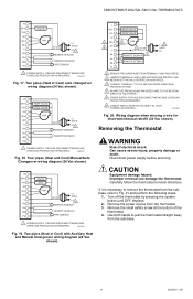
Fig. 2. Terminal Wiring
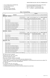
Table 3 provides the terminal wiring for terminal identification.
(2) Push the supply wires back into the junction box.
3. Mounting on page 5 for each model and application.
TB6575/TB8575 DIGITAL FAN COIL THERMOSTATS
(1) Attach the supply wires directly to the terminals on the sub-base and snap the...
Installation Instructions - Page 5
... lead wires attached to any terminals.
5
62-0311-05 b Required when Rs, SB, or Ps is not used on the TB6575B1000 model. A = Electrical heater output
Table 3. • N: Line voltage ground (120/240 Vac) • Ps: Pipe sensor (optional) • R: 24 Vac power • Rs: Remote sensor (optional) • SB: Remote setback (optional)
TB6575/TB8575 DIGITAL FAN COIL THERMOSTATS
•...
Installation Instructions - Page 6
... terminals. 3. Device functions correctly even when not level. 7. TB6575/TB8575 DIGITAL FAN COIL THERMOSTATS
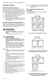
Accessory Wiring
Remote Pipe Sensor Wiring
The remote pipe sensor is used as the remote sensor. Attach pipe sensor to desired values. ing by setting Installer Setup Numbers (ISU) 6 and 7 to the pipe. 4.
SUBBASE
Rs
Sc
TR21
TR21
T
T
T
T
Remote Temperature Sensor...
Installation Instructions - Page 7
...
Sc
SB
REMOTE SETBACK
Ps M27568
Fig. 9.
L
L (HOT)
W/Y
HEAT VALVE
Y/A
COOL VALVE
GI
Gm
FAN
Gh
N
N
Rs
REMOTE SENSOR
Sc
SB
REMOTE SETBACK
Ps M27570
Fig. 11. TB6575/TB8575 DIGITAL FAN COIL THERMOSTATS
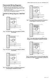
Thermostat Wiring Diagrams
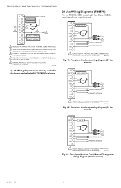
The figures in this section illustrate typical wiring for: • TB6575A1000 and TB6575B1000 fan coil thermostats,
which is 24 Vac powered.
Installation Instructions - Page 8
TB6575/TB8575 DIGITAL FAN COIL THERMOSTATS
. FAN MEDIUM SETTING WILL OPERATE ON HIGH SPEED.
3 CONNECT TERMINAL 7 TO THE MID FAN SPEED WIRE FROM THE PREVIOUS SYSTEM.
4 REWIRE THE PREVIOUS MID SPEED FAN WIRE TO THE NEUTRAL CIRCUIT IN THE SYSTEM.
5 CHANGE INSTALLER SETUP IS CODE 9 TO 2 FOR 2 SPEED FAN CONTROL.
Two pipes Heat-only wiring diagram (24 Vac shown). M27574
Fig. 15.
M27573
...
Installation Instructions - Page 9
...
L1 5 (HOT)
L2
1 REMOVE PRE-WIRED WIRE FROM TERMINAL 5 (MID FAN SPEED).
2 JUMPER TERMINALS 5 AND 6 (MID AND HIGH FAN SPEEDS). TB6575/TB8575 DIGITAL FAN COIL THERMOSTATS
R
W/Y
VALVE
Y/A
GI
Gm
FAN
Gh
24 VAC
L1 (HOT)
C
L2 1
Rs
REMOTE SENSOR
Sc
SB
REMOTE SETBACK
Ps
PIPE SENSOR
1 POWER SUPPLY. Wiring diagram when missing a wire for electromechanical retrofit (24 Vac shown...
Installation Instructions - Page 10
... will damage the thermostat.
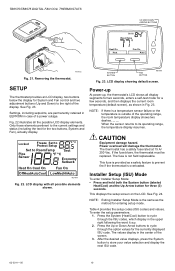
The fuse is outside of a power outage. Installer Setup (ISU) Mode
To enter Installer Setup Mode: &#...FAN BUTTON
M27586
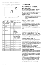
Fig. 23. LCD display showing default screen.
See Fig. 24. The values display in case of the operating range, the room temperature display shows two dashes, - -. This fuse is overloaded.
TB6575/TB8575 DIGITAL FAN COIL THERMOSTATS...
Installation Instructions - Page 11
... Heat when pipe sensor temperature is selected.
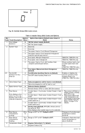
6 Pipe Sensor Threshold for the System Type in
Code Code Description Value
Bold)
1 Line Voltage Selection
0 120 Vac power supply...pipe temperature is 80°F. 90
Changes to 90°F. Setup
TB6575/TB8575 DIGITAL FAN COIL THERMOSTATS
M27585
Fig. 24. Pipe sensor status and water temperature can be checked in test mode (see "Installer...
Installation Instructions - Page 12
... 0°F.
0
1
2
50 to 90
50 to 6. TB6575/TB8575 DIGITAL FAN COIL THERMOSTATS
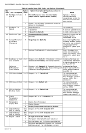
Table 4.
control method for 4-pipe
Auto (ISU 10)
11 CPH Value for system types 5 or 7)
Range is enough torque to 6.
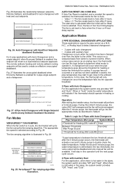
The number selected indicates the maximum times Auxiliary Heating is cycled on per hour (CPH). Installer Setup (ISU) Codes and Options. (Continued)
ISU
Option...
Installation Instructions - Page 13

... 50°F to OFF.
0 Inactive (Default)
Auto Fan Reset is 79°F. TB6575/TB8575 DIGITAL FAN COIL THERMOSTATS
Table 4. Default is not
1
Resets back to option 0 or 5. Installer Setup (ISU) Codes and Options. (Continued)
ISU
Option Option Description (Default value shown in the upper right above the word Test.
2.
Stat cycles On Heat when room temperature reaches...
Installation Instructions - Page 14
... main temperature display to setpoint than 3 seconds. For 4 pipe applications with Auto Changeover and Heat/ Cool Setpoints, when Economy Setback is the same as the method for the duration selected, the thermostat automatically falls back into the Economy Setback. TB6575/TB8575 DIGITAL FAN COIL THERMOSTATS
NOTE: Exiting Installer Test Mode is enabled, the cool setpoint changes to...
Installation Instructions - Page 15
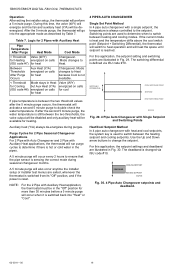
...In this application the system switch only provides "Off" and "Auto". Logic for 2 Pipes with heat and cool setpoints. TB6575/TB8575 DIGITAL FAN COIL THERMOSTATS
Fig. 26 illustrates the relationship between setpoints, Remote Setback, and deadband for auto changeover with Auto Changeover
Pipe Temperature after purge
System Mode
>Threshold for Heating (ISU code #7) Heat
Between Thresholds...
Installation Instructions - Page 16
... changed via ISU code #10.
TB6575/TB8575 DIGITAL FAN COIL THERMOSTATS
Operation:
After exiting the installer setup, the thermostat will go into "Heat" or "Cool". Use the Up and Down arrow buttons to heat operation and will switch to change the setpoint. SWITCHING DIFFERENTIAL
COOL SWITCHING POINT SETPOINT
If pipe temperature is defined via ISU code #10...
Installation Instructions - Page 17
TB6575/TB8575 DIGITAL FAN COIL THERMOSTATS
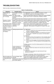
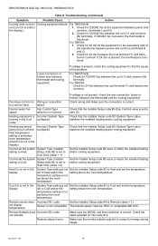
TROUBLESHOOTING
Table 8 provides troubleshooting information. Troubleshooting.
Modify as needed.
Heating or cooling does not come on ) but no operating. Verify
selection is functional. Check wiring. Heat does not turn on . For TB8575A: 1.
Both the heating and Incorrect System Type Check that the Installer Setup code #2 (System Type) ...
Installation Instructions - Page 18
... in
1. Remote setpoint error. TB6575/TB8575 DIGITAL FAN COIL THERMOSTATS
Table 8. For TB6575A/B:
on (Cool On is not in a call for 24 Vac between the cool terminal (Y) and trans- former common.
Fan does not turn Cooling equipment failure.
Check that the Installer Setup code #2 (System Type) value matches the installed heating and/or cooling equipment.
For TB875A...
Installation Instructions - Page 19
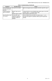
...sure keypad lockout is not Off.
System mode is disabled.
Auto Fan Reset does not activate
Incorrect ISU code.
Set the Installer Setup code #24 to Off.
value = 1). Set the System... not activated when system type is Cool (ISU code #2;
Change System Type. TB6575/TB8575 DIGITAL FAN COIL THERMOSTATS
Table 8.
Calling for Heat/Cool setpoint couldn't be satisfied. Set ISU code #18, ...
Installation Instructions - Page 20

TB6575/TB8575 DIGITAL FAN COIL THERMOSTATS
Automation and Control Solutions Honeywell International Inc. 1985 Douglas Drive North Golden Valley, MN 55422
Honeywell Limited-Honeywell Limitée 35 Dynamic Drive Toronto, Ontario M1V 4Z9 customer.honeywell.com
® U.S. Rev. 10-10 Printed in U.S.A. Registered Trademark © 2010 Honeywell International Inc. 62-0311-05 M.S.
Similar Questions

Economy Setback
My thermostat is on economy setback, how can I get out of this fiction and put the heat back?
My thermostat is on economy setback, how can I get out of this fiction and put the heat back?
(Posted by Esmepark 8 years ago)

Thermostat Needed Battery, Replaced, Does Not Work
replaced batteries, will no let us program it
replaced batteries, will no let us program it
(Posted by dsilkworth 9 years ago)

Honeywell Thermostat Th5220d1003 How To Install Wiring Diagram
(Posted by dgmcum 9 years ago)

We Have Suitepro In Condo. We Switch Heat To Ac. How To Start?
We have SuitePRO in condo. we switch today from heat to AC. we pressed cool but temp going up. Anyth...
We have SuitePRO in condo. we switch today from heat to AC. we pressed cool but temp going up. Anyth...
(Posted by Anonymous-59563 11 years ago)

Fan On Cooling
When setting the control to "Cool", the furnacefan and A/C unit come on immediately for a few second...
When setting the control to "Cool", the furnacefan and A/C unit come on immediately for a few second...
(Posted by garynielsen 13 years ago)