
Dell OptiPlex 755 Support Question
Dell OptiPlex 755 Support Question
Find answers below for this question about Dell OptiPlex 755.Need a Dell OptiPlex 755 manual? We have 3 online manuals for this item!
Question posted by FiliMannet on August 13th, 2014
Optiplex 755 Green Power Light Doesn't Go Off When Powering Down
The person who posted this question about this Dell product did not include a detailed explanation. Please use the "Request More Information" button to the right if more details would help you to answer this question.
Current Answers
Related Dell OptiPlex 755 Manual Pages
Quick Reference
Guide - Page 18
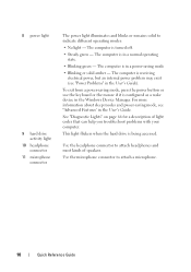
... is in the Windows Device Manager. 8 power light
9 hard drive activity light
10 headphone connector
11 microphone connector
The power light illuminates and blinks or remains solid to attach a microphone.
18
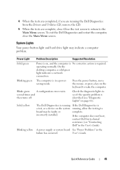
Quick Reference Guide The computer is in the User's Guide. The computer is turned off.
• Steady green -
Use the headphone connector to attach headphones...
Quick Reference
Guide - Page 28
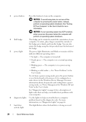
... can also rotate the badge using the slot provided near the bottom of the badge.
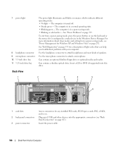
5 power light
The power light illuminates and blinks or remains solid to match the orientation of the badge, press firmly, and turn off .
• Steady green -
The computer is configured as a wake device in the User's Guide. To exit from...
Quick Reference
Guide - Page 39
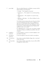
...computer is in a normal operating state.
• Blinking green - The computer is turned off.
• Steady green - The computer is configured as a wake device in the... bay
The power light illuminates and blinks or remains solid to attach a microphone. To exit from a powersaving mode, see "Power Management for a description of speakers.
See "Power Problems" in a power-saving mode....
Quick Reference
Guide - Page 49
....
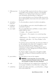
Use the microphone connector to indicate different states:
• No light -
The power light illuminates and blinks or remains solid to attach a microphone. The computer is turned off the computer by pressing the power button. Press this button to turn off .
• Steady green - To ensure proper ventilation, do not turn on page 13 for...
Quick Reference
Guide - Page 53
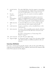
...Connecting a VGA Monitor" on page 53.
10 power connector Insert the AC power adapter plug.
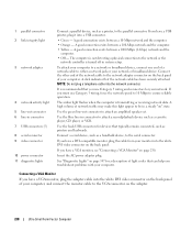
11 diagnostic lights See "Diagnostic Lights" on page 66 for a description of light codes that typically
(5)
remain connected, such as ... into the white DVI video connector on " state.
5 line-out connector
Use the green line-out connector to the serial connector.
9 video connector If you have a DVI-...
Quick Reference
Guide - Page 65
... action is identified (see "Contacting
Dell" in the User's Guide). Blinking yellow A power supply or system board See "Power Problems" in a powersaving mode. Quick Reference Guide
65 operating normally. On the desktop computer, a solid green light indicates a network connection.
Blinks green
A configuration error exists. User's Guide. If the computer does not boot,
contact Dell...
Quick Reference
Guide - Page 66
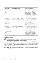
... faulty.
identified (see if the specific problem is identified (see "Diagnostic Lights" on page 66). To help to
card may be faulty or incorrectly see "Diagnostic
Lights" on page 66).
NOTE: After the computer completes POST, all four lights turn off . Solid green power light and no beep code and no beep code but
the computer...
User's Guide - Page 24
... connect occasionally, such as joysticks or cameras, or for more information on page 347.
It is receiving electrical power, but an internal
power problem may exist (see "Diagnostic Lights" on booting to turn off . • Steady green - For more information.
The computer is recommended that typically remain connected, such as a wake device in the...
User's Guide - Page 26
...to the same address. 4 power connector 5 back panel connectors
6 card slots (4)
Insert the power cable. Back Panel Connectors
1
2 34
5
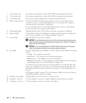
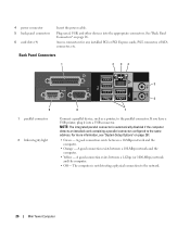
9 1 parallel connector
2 link integrity light
6
8
7
Connect a parallel...and the computer.
• Off - See "Back Panel Connectors" on page 281.
• Green - A good connection exists between a 10-Mbps network and the computer.
• Orange - ...
User's Guide - Page 38
... light adapter)
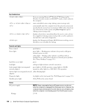
Diagnostic lights
four lights on the front panel (See "Diagnostic Lights" on page 347.)
Standby power light
AUX_PWR on the system board
Power DC power supply:
Wattage Heat dissipation
Voltage Backup battery
NOTE: Power consumption from that allows you to modify the settings
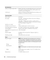
Controls and Lights
Power control
push button
Power light
green light - manual selection power...
User's Guide - Page 88
... use the keyboard or the mouse if it is in a normal operating state. • Blinking green -
Insert the power cable.
88
Desktop Computer The computer is configured as a wake device in the Windows Device Manager. To exit from a power-saving mode, see "Back Panel Connectors" on page 292. Plug serial, USB, and other devices...
User's Guide - Page 89

... most closely matches the AC power available in your location. If you to open the computer cover. Desktop Computer
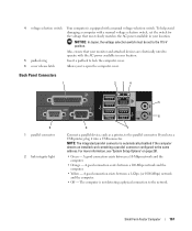
89 Back Panel Connectors
1
2 34
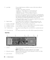
9 1 parallel connector
2 link integrity light
5
6
8
7
Connect ...more information, see "System Setup Options" on page 281.
• Green - NOTE: The integrated parallel connector is automatically disabled if the computer detects an ...
User's Guide - Page 101
... power light
AUX_PWR on integrated network adapter)
green light for 10-Mb operation; in MS-DOS® mode, restarts (reboots) the computer
starts embedded system setup (during system start-up only)
automatically starts the computer from the network environment specified by the remote boot environment (PXE) rather than from the AC power source.
280 W
Desktop Computer...
User's Guide - Page 166
...a normal operating state. • Blinking green - Can contain an optional slimline floppy drive or optional media card reader.
Insert a CD or DVD (if supported) into the appropriate connectors (see "Power Management for a description of speakers. The computer is in the Windows Device Manager. See "Power Problems" on page 292.
7 power light
8 headphone connector 9 microphone connector...
User's Guide - Page 167
...
9 1 parallel connector
2 link integrity light
5
6
8
7
Connect a parallel device, such as a printer, to the network. For more information, see "System Setup Options" on page 281.
• Green - A good connection exists between a...Yellow - 4 voltage selection switch Your computer is equipped with the AC power available in your location. NOTICE: In Japan, the voltage selection switch must...
User's Guide - Page 178
...
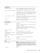
hard drive access light
green
Link light
solid green light indicates network connection
Link integrity light (on integrated network adapter)
green light for a 1000-Mb (1-Gb) operation
Activity light (on integrated network yellow blinking light adapter)
Diagnostic lights
four lights on the front panel (See "Dell Diagnostics" on page 353.)
Standby power light
AUX_PWR on state. blinking...
User's Guide - Page 228
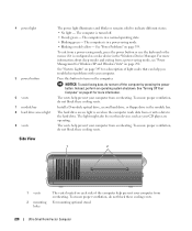
... data from overheating.
To ensure proper ventilation, do not block these cooling vents.
For more information. 4 power light
5 power button 6 vents 7 module bay 8 hard drive access light 9 vents
The power light illuminates and blinks or remains solid to turn off . • Steady green - The computer is configured as your CD player are operating. The hard drive access...
User's Guide - Page 230
...click indicates that typically remain connected, such as printers and keyboards.
Use the green line-out connector to attach a record/playback device such as a cassette ... link integrity light
3 network adapter
4 network activity light 5 line-out connector 6 line-in connector 7 USB connectors (5) 8 serial connector 9 video connector 10 power connector 11 diagnostic lights
Connect a parallel...
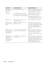
User's Guide - Page 346
...
be faulty.
See "Beep Codes" on page 350 for technical assistance (see "Diagnostic Lights" on page 370).
See "Video and Monitor Problems" on diagnosing the beep code.
Blinking yellow
A power supply or system board failure has occurred.
Solid green power light and no beep code and no beep code but the computer locks up during...
User's Guide - Page 373
... away from the receiver.
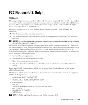
• Plug the system into a different outlet so that may cause interference with the FCC regulations:
• Product name: Dell™ OptiPlex™ 755
• Model numbers: DCTR, DCNE, DCSM, DCCY
• Company name: Dell Inc.
If necessary, consult a representative of the following information is subject to correct...
Similar Questions

Dell Optiplex 755 Orange Power Light Won't Turn Green
(Posted by miPDay 10 years ago)


Dell Optiplex Gx620 Won't Turn On Green Flashing Lights
(Posted by Sunnyme 10 years ago)

When I Plug The Power Into My Optiplex 755 The Power Button Flashes And Makes A
noise
noise
(Posted by Diaat 10 years ago)