AIWA CDC-R104 Support Question
AIWA CDC-R104 Support Question
Find answers below for this question about AIWA CDC-R104.Need a AIWA CDC-R104 manual? We have 1 online manual for this item!
Question posted by jcatz on February 19th, 2013
How To Set/change Clock Time
Unable to find clock/time settings from menu. Appreciate any help on how to set/change clock on the player. Thanks!
Current Answers
Related AIWA CDC-R104 Manual Pages
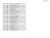
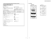
Service Manual - Page 2
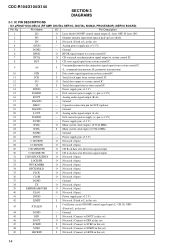
CDC-R104/X104/X144
SECTION 3 DIAGRAMS
3-1. Analog power supply pin (+3.3 V)
5
DGND
-
Power supply pin (+3.3 V)
23
XTAL
O Main system clock output (16.9344 MHz)
24
XTAL
I
(Fixed at L in this set)
44
DGND
- Ground
26
DVDD
- Power supply pin (+3.3 V)
42
LIMIT
I Not used . (Fixed at L in this set... V)
16
ROUT
O Analog audio signal output (R-ch)
17
...
Service Manual - Page 3
...AGCI RFO ATEST C3T AGND
A C B D F E VREFIN AVDD REFOUT REFC FE- I /O
Pin Description
O Not used . (Fixed at L in this set )
- I Focus error signal amplifier inversion input
O Focus error signal amplifier output
I Not used . (Open)
- TD+ TD- SD+ SD- I ...90 91 92 93 94 95 96 97 98 99 100
Pin Name LRCK DVDD FD+ FD-
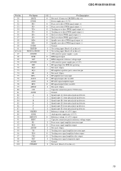
CDC-R104/X104/X144
Pin No. 50 51 52 53 54 55 56 57 58 59 60 61
62...
Service Manual - Page 4
... input
24
ATT
O Audio mute control signal output
25
XKEYON
O Key power supply control signal output Not used in this set. (Open)
26
NCO
O Not used in this set. (Open)
27
KEYACK... Not used in this set.
10
VDD1
- Pin Name
I Low speed operation clock signal input (32.768 kHz)
16
XOUT
O Low speed operation clock signal output (32.768 kHz)
17
VDD2
- CDC-R104/X104/X144
• ...
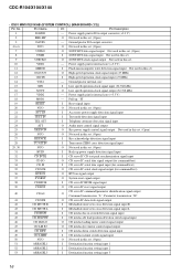
Service Manual - Page 5
...Ground pin for I/O port (+3.3 V)
"L" input: two color change signal output (Cut off O
"L" output: LCD unit and key confusion, power on
O Not used in this set . (Open)
- I Key signal input (EJECT, OFF...
17
17
CDC-R104/X104/X144 Ground pin for I/O port
O Tuner mute control signal output
O Not used in this set. (Open)
O Noise mask signal output
O Serial clock signal output for...
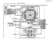
Service Manual - Page 6
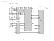
... CD_A0 39 CD RST
SYSTEM CONTROL IC501 (1/3)
48 CD_DSW 45 CD_SELFSW 44 CD_INSW 49 CD_LIMIT
46 CD LM LO 47 CD LM EJ
18
18 CDC-R104/X104/X144
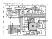
3-2.
DETECTOR PD1 PD1
PD2
PD2
82 A 84 B 83 C 85 D
RFO 78
77 AGCI AGCO 76
71 RFI
EFM 68
RF AMP,DIGITAL SERVO...
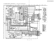
Service Manual - Page 7
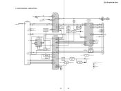
... RST 37
LOW VOLTAGE DETECT Q581
BACK UP+3.3V
TU+5V
TU+5V REG Q1
AUDIO+8.3V
D580
BATT
OVER VOLTAGE DETECT Q580
D581
• R-CH is omitted due to same as L-CH. • Signal Path
: CD PLAY : FM : AM/MW/LW
: AUX
19
19
MAIN SECTION - CDC-R104/X104/X144
3-3. BLOCK DIAGRAM -
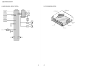
Service Manual - Page 8
...
PANEL+10V
LED DRIVE Q902,903
LED901-920
S702 RESET
19 RESET
X502 32.768kHz
15 XIN 16 XOUT
OSCIN 13 OSCOUT 12
X501 27MHz
3-5. CDC-R104/X104/X144
3-4.
Service Manual - Page 9
... - (MODE: CD PLAY)
1
1.2Vp-p
16.9344MHz
IC1 wd (XTAL) 2
1.6Vp-p
IC1 uj (AGCI) 3
0V Approx. 620mVp-p
IC1 od (FEO) 4
0V Approx. 200mVp-p
IC1 oh (TEO)
CDC-R104/X104/X144
-
Service Manual - Page 10
... C74
TP71 TP70 TP73 TP72
C79 R85 R84 C78 R83 R82 C77 R81 R80 C76 R79 R78
TP75 TP74
C75
23
23
C19 JR90 JR91
CDC-R104/X104/X144
TP65
TP64
TP63
TP62
TP61
TP60
R45
TP59
R44
TP58
TP57
TP56
TP55
TP54
TP48
TP52
TP51
TP53
TP49
TP50
TP47
TP46
TP45...
Service Manual - Page 11
SCHEMATIC DIAGRAM - CDC-R104/X104/X144
• Refer to page 29 for Waveforms. 3-10. MAIN SECTION (1/2) - • Refer to page 21 for IC Block Diagrams.
TU1
J1
C3 C1 ...
Service Manual - Page 12
...
R582 R583
D703 D702
R701
R731
R732
R735
C732 R734
C731 R733
L373
L374 L372 L731
D731 CN701
D711
D712
C704
(Page 28)
25
25
CDC-R104/X104/X144 SCHEMATIC DIAGRAM -
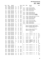
Service Manual - Page 15
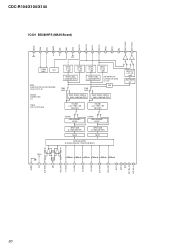
CDC-R104/X104/X144
IC401 BD3809FS (MAIN Board)
DGND SDA SCL MUTE SEL ADJ VCC OUT-FR OUT-RR OUT-FL OUT-RL BP22 BP12 NC OUT-...
Service Manual - Page 16
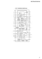
CDC-R104/X104/X144
IC750 TDA8589BJ/N2 (MAIN Board)
TAB 1 OUT-FL- 3
OUT-FL+ 5 OUT-RL- 7 OUT-RL+ 9
IN-RL 11 S-GND 13 IN-RR 15 OUT-...
Service Manual - Page 17
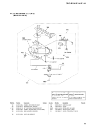
...-447-A MOTOR ASSY, SL (SLED) 1-571-099-11 SWITCH (1 KEY) (LIMIT) 7-627-850-77 SCREW, PRECISION +P 1.4X1.8
Remark
35
CD MECHANISM SECTION (2) (MG-611XC-186//Q)
CDC-R104/X104/X144
154
(including M901)
SW4
155 156
157
M902
#5 not supplied
158
not supplied
not supplied
153
not supplied
not supplied
152 151
The...
Service Manual - Page 18
...LCD), REFLECTION
LED901 6-500-509-01 LED CL-165D/PG-D-T (MENU) LED902 6-500-509-01 LED CL-165D/PG-D-T (MENU) LED903 6-500-437-01 LED CL-165D/SYG-D-T (OFF) ...< JACK >
J601 1-817-308-11 JACK (AUX IN
Ref. No. CDC-R104/X104/X144
AUX KEY
NOTE: • Due to standardization, replacements in
the...the diagrams or the components used on the set. • -XX and -X mean standardized parts, so they are seldom ...
Service Manual - Page 19
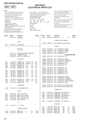
...3.3K R995 1-216-827-11 METAL CHIP 3.3K R996 1-216-827-11 METAL CHIP 3.3K
CDC-R104/X104/X144 KEY MAIN
Remark Ref. Part No. No.
Part No. No. Ref.
Description
Remark...-884-31 SWITCH, TACTILE (SEEK + > M)
5% 1/10W
5% 1/10W
S911 1-478-474-11 ENCODER, ROTARY (VOLUME/PUSH-MENU)
5% 1/10W
S912 1-771-884-31 SWITCH, TACTILE (DSPL)
5% 1/10W
S913 1-771-884-31 SWITCH, TACTILE (H-BASS)
...
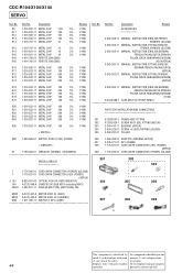
Service Manual - Page 24
..., INSTRUCTION (ENGLISH,GERMAN,
5% 1/10W
FRENCH,ITALIAN,DUTCH,SPANISH,
5% 1/10W
POLISH,CZECH,HUNGARIAN,RUSSIAN)
5% 1/10W
(R104)
5% 1/10W
X-3384-688-1 CASE ASSY (for FRONT PANEL)
5% 1/10W
5% 1/10W
PARTS FOR INSTALLATION AND CONNECTIONS...with part number Ne les remplacer que par une piéce
specified.
CDC-R104/X104/X144 SERVO
Ref.
Part No. la sécurité.
44...
Similar Questions

Aiwa Cdc-x227 Plug
What does the back of the plug look like where the wires go into it
What does the back of the plug look like where the wires go into it
(Posted by darrellbraun9 4 years ago)

Cdc-x2170 Reset Button
Is there a reset button & how should i do that?
Is there a reset button & how should i do that?
(Posted by fychkroy 10 years ago)

I Need A Pinout Diagram For A Cdc-x144
no Harness But Need To Wire The Radio In Hard
no Harness But Need To Wire The Radio In Hard
(Posted by JIMMYKAYLA77 10 years ago)

Wiring Harness For One Of The Aiwa Cdc-x517myu?
Where can I find a wiring harness for this stereo? Or what wiring harness would fit this stereo?
Where can I find a wiring harness for this stereo? Or what wiring harness would fit this stereo?
(Posted by Hotrod8000 10 years ago)

Aiwa Cdc X504mp3, Looking For The Wiring Harness
instruction manuals or diagram showing wire diagram for speaker set up
instruction manuals or diagram showing wire diagram for speaker set up
(Posted by curtistice1 11 years ago)