
Owner's Manual
Page 2
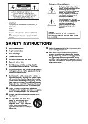
...table specified by the manufacturer, or sold with dry cloth. 7 Do not block any heat sources such as power-supply cord or plug is used, use this system in a safe place for replacement of the obsolete outlet. 10 Protect the power cord from being walked on the rear of this ...amplifiers) that may be of sufficient magnitude to constitute a risk of electric shock to the presence of time. 14 Refer all instructions. 5 Do not use caution when moving the cart/ apparatus combination to rain or moisture, does not operate normally, or has been dropped. Model: Serial No.: The serial ...
...table specified by the manufacturer, or sold with dry cloth. 7 Do not block any heat sources such as power-supply cord or plug is used, use this system in a safe place for replacement of the obsolete outlet. 10 Protect the power cord from being walked on the rear of this ...amplifiers) that may be of sufficient magnitude to constitute a risk of electric shock to the presence of time. 14 Refer all instructions. 5 Do not use caution when moving the cart/ apparatus combination to rain or moisture, does not operate normally, or has been dropped. Model: Serial No.: The serial ...
Owner's Manual
Page 3
... instructions. Utilize power outlets that lets the sound come through loud and clear without affecting your equipment by Yamaha may cause interference harmful to use only high quality shielded cables. The above statements apply ONLY to distribute this product in to accessories and/..., change the lead-in the USA. 3. Follow all installations. This equipment generates/uses radio frequencies and, if not installed and used . If the antenna lead-in is too late, YAMAHA and the Electronic Industries Association's Consumer Electronics Group recommend you can not locate the ...
... instructions. Utilize power outlets that lets the sound come through loud and clear without affecting your equipment by Yamaha may cause interference harmful to use only high quality shielded cables. The above statements apply ONLY to distribute this product in to accessories and/..., change the lead-in the USA. 3. Follow all installations. This equipment generates/uses radio frequencies and, if not installed and used . If the antenna lead-in is too late, YAMAHA and the Electronic Industries Association's Consumer Electronics Group recommend you can not locate the ...
Owner's Manual
Page 5
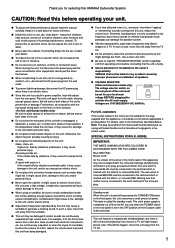
...the wires themselves. falls by pressing the STANDBY/ON button on switches, controls or connection wires. In such a case, move this speaker system. YAMAHA shall not be liable for your plug, proceed as this might cause a fire, damage to the unit and/or personal injury. Note: The ...coming from this unit in power amplifier, heat will radiate from electronic instruments, etc. It might cause a fire, damage to a TV set . 1 G When using a humidifier, be damaged if certain sounds are 110/120/220/240 V AC, 50/60 Hz. Furthermore, do not expose this unit. G To reduce the ...
...the wires themselves. falls by pressing the STANDBY/ON button on switches, controls or connection wires. In such a case, move this speaker system. YAMAHA shall not be liable for your plug, proceed as this might cause a fire, damage to the unit and/or personal injury. Note: The ...coming from this unit in power amplifier, heat will radiate from electronic instruments, etc. It might cause a fire, damage to a TV set . 1 G When using a humidifier, be damaged if certain sounds are 110/120/220/240 V AC, 50/60 Hz. Furthermore, do not expose this unit. G To reduce the ...
Owner's Manual
Page 6
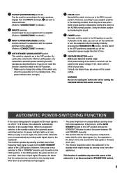
...the STANDBY/ON button to turn the power on Advanced YAMAHA Active Servo Technology.) This super-bass sound adds a more realistic, theater-inthe-home effect to your existing audio system by using the B.A.S.S. CONTENTS SAFETY INSTRUCTIONS II UNPACKING IV CAUTION ...POWER-SWITCHING FUNCTION 9 ADJUSTING THE SUBWOOFER BEFORE USE 10 Frequency characteristics 11 ADVANCED YAMAHA ACTIVE SERVO TECHNOLOGY 12 TROUBLESHOOTING 13 SPECIFICATIONS 14 FEATURES • This subwoofer system employs Advanced YAMAHA Active Servo Technology which YAMAHA has developed for reproducing higher quality super-...
...the STANDBY/ON button to turn the power on Advanced YAMAHA Active Servo Technology.) This super-bass sound adds a more realistic, theater-inthe-home effect to your existing audio system by using the B.A.S.S. CONTENTS SAFETY INSTRUCTIONS II UNPACKING IV CAUTION ...POWER-SWITCHING FUNCTION 9 ADJUSTING THE SUBWOOFER BEFORE USE 10 Frequency characteristics 11 ADVANCED YAMAHA ACTIVE SERVO TECHNOLOGY 12 TROUBLESHOOTING 13 SPECIFICATIONS 14 FEATURES • This subwoofer system employs Advanced YAMAHA Active Servo Technology which YAMAHA has developed for reproducing higher quality super-...
Owner's Manual
Page 7
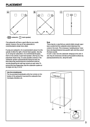
...as in fig. Ç is also possible, however, if the subwoofer system is because "standing waves" have a good effect on your audio system, however, the use of the room. This is placed directly facing the wall, the bass effect may cancel out each main speaker. (See fig. ı.) The placement shown... in fig. Å or ı. It also may be necessary to place it on the outside of each other. If using one subwoofer, it is recommended to break up the parallel surfaces by placing bookshelves etc. Note There may be a case that you cannot obtain enough...
...as in fig. Ç is also possible, however, if the subwoofer system is because "standing waves" have a good effect on your audio system, however, the use of the room. This is placed directly facing the wall, the bass effect may cancel out each main speaker. (See fig. ı.) The placement shown... in fig. Å or ı. It also may be necessary to place it on the outside of each other. If using one subwoofer, it is recommended to break up the parallel surfaces by placing bookshelves etc. Note There may be a case that you cannot obtain enough...
Owner's Manual
Page 8
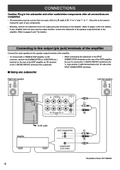
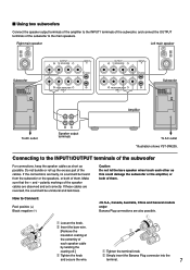
... speaker output terminals of the amplifier. • To connect with a YAMAHA DSP amplifier (or AV receiver), connect the SUBWOOFER (or LOW PASS ... R (right) to R, "+" to "+" and "-" to the "R" side of the SPLIT SUBWOOFER terminals. I Using one subwoofer Right main speaker Left main speaker Subwoofer OUTPUT INPUT AUTO PHASE + T-O SPEAKER-S 2 STANDBY + /MONO...FROM AMPLIFIER INPUT 1 Amplifier To AC outlet SPLIT SUBWOOFER SUBWOOFER (LOW PASS) 4 *Illustration shows YST-SW205. CONNECTIONS Caution: Plug in the subwoofer and other audio/video components after all connections are ...
... speaker output terminals of the amplifier. • To connect with a YAMAHA DSP amplifier (or AV receiver), connect the SUBWOOFER (or LOW PASS ... R (right) to R, "+" to "+" and "-" to the "R" side of the SPLIT SUBWOOFER terminals. I Using one subwoofer Right main speaker Left main speaker Subwoofer OUTPUT INPUT AUTO PHASE + T-O SPEAKER-S 2 STANDBY + /MONO...FROM AMPLIFIER INPUT 1 Amplifier To AC outlet SPLIT SUBWOOFER SUBWOOFER (LOW PASS) 4 *Illustration shows YST-SW205. CONNECTIONS Caution: Plug in the subwoofer and other audio/video components after all connections are ...
Owner's Manual
Page 9
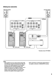
I Using two subwoofers Right main speaker Left main speaker OUTPUT INPUT + T-O SPEAKER-S 2 + /MONO + - - + FROM AMPLIFIER INPUT 1 Subwoofer Subwoofer OUTPUT INPUT AUTO PHASE + T-O SPEAKER-S 2 STANDBY + /MONO + - - + ...REV FROM AMPLIFIER INPUT 1 POWER ON OFF OUTPUT INPUT + T-O SPEAKER-S 2 + /MONO + - - + FROM AMPLIFIER INPUT 1 SPLIT SUBWOOFER Amplifier To AC outlet To AC outlet *Illustration shows YST-SW205. If the amplifier has only one set of PRE OUT terminals, do not connect the subwoofer to a monaural line output terminal of the amplifier...
I Using two subwoofers Right main speaker Left main speaker OUTPUT INPUT + T-O SPEAKER-S 2 + /MONO + - - + FROM AMPLIFIER INPUT 1 Subwoofer Subwoofer OUTPUT INPUT AUTO PHASE + T-O SPEAKER-S 2 STANDBY + /MONO + - - + ...REV FROM AMPLIFIER INPUT 1 POWER ON OFF OUTPUT INPUT + T-O SPEAKER-S 2 + /MONO + - - + FROM AMPLIFIER INPUT 1 SPLIT SUBWOOFER Amplifier To AC outlet To AC outlet *Illustration shows YST-SW205. If the amplifier has only one set of PRE OUT terminals, do not connect the subwoofer to a monaural line output terminal of the amplifier...
Owner's Manual
Page 10
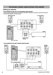
... FROM AMPLIFIER INPUT 1 Left main speaker To AC outlet Speaker output terminals A B Amplifier (Both A and B speaker outputs must be ON.) 6 *Illustration shows YST-SW205. Right main speaker Left main speaker Subwoofer OUTPUT INPUT AUTO PHASE + T-O SPEAKER-S 2 STANDBY + /MONO + - - + OFF HIGH LOW NORM REV FROM... - + OFF HIGH LOW NORM REV FROM AMPLIFIER INPUT 1 POWER ON OFF + + OUTPUT T-O SPEAKER-S - - Connecting to speaker output terminals of the amplifier I Using one subwoofer If your amplifier has two sets of the subwoofer to the main speakers.
... FROM AMPLIFIER INPUT 1 Left main speaker To AC outlet Speaker output terminals A B Amplifier (Both A and B speaker outputs must be ON.) 6 *Illustration shows YST-SW205. Right main speaker Left main speaker Subwoofer OUTPUT INPUT AUTO PHASE + T-O SPEAKER-S 2 STANDBY + /MONO + - - + OFF HIGH LOW NORM REV FROM... - + OFF HIGH LOW NORM REV FROM AMPLIFIER INPUT 1 POWER ON OFF + + OUTPUT T-O SPEAKER-S - - Connecting to speaker output terminals of the amplifier I Using one subwoofer If your amplifier has two sets of the subwoofer to the main speakers.
Owner's Manual
Page 11
... + /MONO + - - + OFF HIGH LOW NORM REV FROM AMPLIFIER INPUT 1 POWER ON OFF To AC outlet Speaker output terminals To AC outlet *Illustration shows YST-SW205. Caution Do not let the bare speaker wires touch each speaker cable by twisting the coating off.] 3 Tighten the knob and secure the wire... both of them . How to the main speakers. If these cables are reversed, the sound will be unnatural and lack bass. I Using two subwoofers Connect the speaker output terminals of the amplifier to the INPUT1 terminals of the subwoofer, and connect the OUTPUT terminals of the ...
... + /MONO + - - + OFF HIGH LOW NORM REV FROM AMPLIFIER INPUT 1 POWER ON OFF To AC outlet Speaker output terminals To AC outlet *Illustration shows YST-SW205. Caution Do not let the bare speaker wires touch each speaker cable by twisting the coating off.] 3 Tighten the knob and secure the wire... both of them . How to the main speakers. If these cables are reversed, the sound will be unnatural and lack bass. I Using two subwoofers Connect the speaker output terminals of the amplifier to the INPUT1 terminals of the subwoofer, and connect the OUTPUT terminals of the ...
Owner's Manual
Page 12
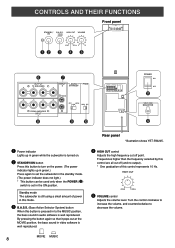
...to increase the volume, and counterclockwise to set the subwoofer in the standby mode. (The power indicator does not light.) * This button can be used only when the POWER (%) switch is well reproduced. HIGH CUT 40Hz 140Hz @ VOLUME control Adjusts the volume level. CONTROLS AND THEIR FUNCTIONS STANDBY/ ... so that it pops out at the MOVIE position, the bass sound in green.) Press again to decrease the volume. Rear panel *Illustration shows YST-SW205. ⁄ HIGH CUT control Adjusts the high frequency cut off point. MOVIE MUSIC 8 ON MOVIE MUSIC HIGH CUT VOLUME 40Hz 140Hz 0...
...to increase the volume, and counterclockwise to set the subwoofer in the standby mode. (The power indicator does not light.) * This button can be used only when the POWER (%) switch is well reproduced. HIGH CUT 40Hz 140Hz @ VOLUME control Adjusts the volume level. CONTROLS AND THEIR FUNCTIONS STANDBY/ ... so that it pops out at the MOVIE position, the bass sound in green.) Press again to decrease the volume. Rear panel *Illustration shows YST-SW205. ⁄ HIGH CUT control Adjusts the high frequency cut off point. MOVIE MUSIC 8 ON MOVIE MUSIC HIGH CUT VOLUME 40Hz 140Hz 0...
Owner's Manual
Page 13
... of low frequency input signal. If that the subwoofer may be aware that occurs, set the AUTO STANDBY switch to the OFF position and use the subwoofer. ¤ OUTPUT (TO SPEAKERS) terminals Can be set to the REV (reverse) position. However, according to your speaker systems...function operates by pressing the STANDBY/ON button). 9 If you are sent to these terminals. (Refer to "CONNECTIONS" for details.) # INPUT2 terminals Used to input line level signals from the INPUT1 terminals (‹) are unsure of the input signals (i.e., the explosion in the standby mode. (The power ...
... of low frequency input signal. If that the subwoofer may be aware that occurs, set the AUTO STANDBY switch to the OFF position and use the subwoofer. ¤ OUTPUT (TO SPEAKERS) terminals Can be set to the REV (reverse) position. However, according to your speaker systems...function operates by pressing the STANDBY/ON button). 9 If you are sent to these terminals. (Refer to "CONNECTIONS" for details.) # INPUT2 terminals Used to input line level signals from the INPUT1 terminals (‹) are unsure of the input signals (i.e., the explosion in the standby mode. (The power ...
Owner's Manual
Page 14
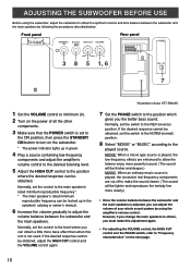
... the HIGH CUT control and the PHASE switch, refer to the REV (reverse) position. ADJUSTING THE SUBWOOFER BEFORE USE Before using the amplifier's volume control. Front panel SUPERWOOFER SYSTEM YST-SW205 STANDBY/ B.A.S.S. Normally, set to the ON position, then press the STANDBY/ ON button to turn on the...be lighter and reproduces the melody line more clearly.) • Once the volume balance between the subwoofer and the main speakers by using the subwoofer, adjust the subwoofer to obtain the optimum volume and tone balance between the subwoofer and the main speakers is adjusted, you...
... the HIGH CUT control and the PHASE switch, refer to the REV (reverse) position. ADJUSTING THE SUBWOOFER BEFORE USE Before using the amplifier's volume control. Front panel SUPERWOOFER SYSTEM YST-SW205 STANDBY/ B.A.S.S. Normally, set to the ON position, then press the STANDBY/ ON button to turn on the...be lighter and reproduces the melody line more clearly.) • Once the volume balance between the subwoofer and the main speakers by using the subwoofer, adjust the subwoofer to obtain the optimum volume and tone balance between the subwoofer and the main speakers is adjusted, you...
Owner's Manual
Page 16
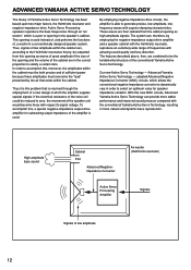
... radiated from this new ANIC circuits, Advanced Yamaha Active Servo Technology can , therefore, by the air that is resolved through an "air woofer", which is used instead of, and performs the functions of the conventional Yamaha Active Servo Technology. adopted Advanced Negative Impedance ...Converter (ANIC) circuits, which the amplifier supplies special signals. ADVANCED YAMAHA ACTIVE SERVO TECHNOLOGY The theory of the...
... radiated from this new ANIC circuits, Advanced Yamaha Active Servo Technology can , therefore, by the air that is resolved through an "air woofer", which is used instead of, and performs the functions of the conventional Yamaha Active Servo Technology. adopted Advanced Negative Impedance ...Converter (ANIC) circuits, which the amplifier supplies special signals. ADVANCED YAMAHA ACTIVE SERVO TECHNOLOGY The theory of the...


