

Owner's Manual
Page 6
... Input Channel Settings 57 Copying & Swapping Channel Settings 59 Input Channel Block Diagram 60 6 EQ 61 About the 01V EQ 62 Adjusting the EQ 63 EQ Specs 66 Bypassing the EQ 66 Resetting the EQ 66 EQ Library 67 Preset EQ Program List 67 Storing EQ Programs 68 Recalling EQ Programs 69... & the Stereo Output 88 Option I/O & the Stereo Output 88 Omni Outs & the Stereo Output 88 Solo & the Stereo Output 88 Monitoring the Stereo Output 88 01V-Owner's Manual
... Input Channel Settings 57 Copying & Swapping Channel Settings 59 Input Channel Block Diagram 60 6 EQ 61 About the 01V EQ 62 Adjusting the EQ 63 EQ Specs 66 Bypassing the EQ 66 Resetting the EQ 66 EQ Library 67 Preset EQ Program List 67 Storing EQ Programs 68 Recalling EQ Programs 69... & the Stereo Output 88 Option I/O & the Stereo Output 88 Omni Outs & the Stereo Output 88 Solo & the Stereo Output 88 Monitoring the Stereo Output 88 01V-Owner's Manual

Owner's Manual
Page 58
...signal processing. Panpot operation depends on the selected Pan mode. OR Use the [SETUP] button to locate SETUP page 4, as a stereo pair. 01V-Owner's Manual The highlighted switch and STEREO label show that the input channels are paired: attenuators, EQ, dynamics, delays, [ON], and [SEL]... now configured as shown below, and use the cursor buttons to select a pairing mode, and then press the [ENTER] button. RESET BOTH-Reset both input channels simultaneously. The following dialog box appears. Press the [SEL] button of input channel 2 to input channel 1. CH 2 ->...
...signal processing. Panpot operation depends on the selected Pan mode. OR Use the [SETUP] button to locate SETUP page 4, as a stereo pair. 01V-Owner's Manual The highlighted switch and STEREO label show that the input channels are paired: attenuators, EQ, dynamics, delays, [ON], and [SEL]... now configured as shown below, and use the cursor buttons to select a pairing mode, and then press the [ENTER] button. RESET BOTH-Reset both input channels simultaneously. The following dialog box appears. Press the [SEL] button of input channel 2 to input channel 1. CH 2 ->...

Owner's Manual
Page 67
EQ 61 EQ 6 In this chapter... About the 01V EQ 62 Adjusting the EQ 63 EQ Specs 66 Bypassing the EQ 66 Resetting the EQ 66 EQ Library 67 Preset EQ Program List 67 Storing EQ Programs 68 Recalling EQ Programs 69 Editing EQ Program Titles 70 Preset EQ Program Parameters 71 01V-Owner's Manual
EQ 61 EQ 6 In this chapter... About the 01V EQ 62 Adjusting the EQ 63 EQ Specs 66 Bypassing the EQ 66 Resetting the EQ 66 EQ Library 67 Preset EQ Program List 67 Storing EQ Programs 68 Recalling EQ Programs 69 Editing EQ Program Titles 70 Preset EQ Program Parameters 71 01V-Owner's Manual

Owner's Manual
Page 72
....1 kHz (1/12 octave steps, 120 steps) HPF, 10.0-0.10 LPF, 10.0-0.10 Q (41 steps), 10.0-0.10 (41 steps) (41 steps), L.SHELF H.SHELF 1. ENTER Resetting the EQ To reset all the EQ parameters on input channels 17 through 24). 2. Gain (G) Frequency (F) Q Low 0 dB 125 Hz L.SHELF Lo-Mid1 0 dB 1.00 kHz 0.70 Hi... values. Low Lo-Mid1 Hi-Mid1 High Gain (G) Frequency (F) -18.0 dB to their gain controls function as filter on input channels 17 through 24). 01V-Owner's Manual
....1 kHz (1/12 octave steps, 120 steps) HPF, 10.0-0.10 LPF, 10.0-0.10 Q (41 steps), 10.0-0.10 (41 steps) (41 steps), L.SHELF H.SHELF 1. ENTER Resetting the EQ To reset all the EQ parameters on input channels 17 through 24). 2. Gain (G) Frequency (F) Q Low 0 dB 125 Hz L.SHELF Lo-Mid1 0 dB 1.00 kHz 0.70 Hi... values. Low Lo-Mid1 Hi-Mid1 High Gain (G) Frequency (F) -18.0 dB to their gain controls function as filter on input channels 17 through 24). 01V-Owner's Manual

Owner's Manual
Page 90
... dedicated 12-segment main stereo meters, with the HOME, OPTION I/O, and main stereo meters. Peak Hold The Peak Hold function works with Peak Hold. To reset the Peak Hold function, turn the Peak Hold function on or off and then on page 116 for peak levels. 1. See "Assigning Omni Outs" on... again. 01V-Owner's Manual Use the PARAMETER wheel, [-1/DEC] and [+1/INC] buttons, or [ENTER] button to turn it 's turned on, the meter segments lit by the metering...
... dedicated 12-segment main stereo meters, with the HOME, OPTION I/O, and main stereo meters. Peak Hold The Peak Hold function works with Peak Hold. To reset the Peak Hold function, turn the Peak Hold function on or off and then on page 116 for peak levels. 1. See "Assigning Omni Outs" on... again. 01V-Owner's Manual Use the PARAMETER wheel, [-1/DEC] and [+1/INC] buttons, or [ENTER] button to turn it 's turned on, the meter segments lit by the metering...

Owner's Manual
Page 107
Making Aux Send Pairs 1. Use the [SETUP] button to select a pairing mode, and then press the [ENTER] button. RESET BOTH-Reset both aux sends operate independently. 01V-Owner's Manual Use the cursor buttons to locate SETUP page 4, as a stereo pair. Releasing Aux Send Pairs 1. Select OK, and then press the [ENTER] button. ...
Making Aux Send Pairs 1. Use the [SETUP] button to select a pairing mode, and then press the [ENTER] button. RESET BOTH-Reset both aux sends operate independently. 01V-Owner's Manual Use the cursor buttons to locate SETUP page 4, as a stereo pair. Releasing Aux Send Pairs 1. Select OK, and then press the [ENTER] button. ...

Owner's Manual
Page 116
... pair 1/2 or 3/4, and then press the [ENTER] button. Use the cursor buttons to select a pairing mode, and then press the [ENTER] button. RESET BOTH-Reset both bus outs operate independently. 01V-Owner's Manual The highlighted switch and STEREO label show that the bus outs are linked for stereo signal processing. BUS 1 -> 2-Copy the...
... pair 1/2 or 3/4, and then press the [ENTER] button. Use the cursor buttons to select a pairing mode, and then press the [ENTER] button. RESET BOTH-Reset both bus outs operate independently. 01V-Owner's Manual The highlighted switch and STEREO label show that the bus outs are linked for stereo signal processing. BUS 1 -> 2-Copy the...

Owner's Manual
Page 187
... indicator appears in the Memory area of the display, indicating that the current mix settings (i.e., those in the Memory area are stored when the 01V is turned off . The Edit Buffer settings are the MIDI and HOST indicators, which appear when MIDI data is received at the MIDI IN ... mix settings. You can be stored to be protected individually against accidental overwriting. To reset all mix settings to 99 can recall it, but you cannot store it 's a read-only memory and contains the initial 01V settings. Scene Memory Display Area The scene memory area of the display shows the number...
... indicator appears in the Memory area of the display, indicating that the current mix settings (i.e., those in the Memory area are stored when the 01V is turned off . The Edit Buffer settings are the MIDI and HOST indicators, which appear when MIDI data is received at the MIDI IN ... mix settings. You can be stored to be protected individually against accidental overwriting. To reset all mix settings to 99 can recall it, but you cannot store it 's a read-only memory and contains the initial 01V settings. Scene Memory Display Area The scene memory area of the display shows the number...

Owner's Manual
Page 196
...other banks are active only when REMOTE page 1 is displayed, faders and [ON] buttons perform the functions assigned to its initial assignments. 01V-Owner's Manual See "Bulk Dump" on page 232 for example, can be used to control bus out master levels, which do not have.... 2. While this page is displayed. Available functions for the faders and [ON] buttons are listed in banks 1 through 4, for more information. To reset a bank back to them . Input channel faders 1 through 4. 1. Custom assignments are stored in their respective banks when other than their regular functions. ...
...other banks are active only when REMOTE page 1 is displayed, faders and [ON] buttons perform the functions assigned to its initial assignments. 01V-Owner's Manual See "Bulk Dump" on page 232 for example, can be used to control bus out master levels, which do not have.... 2. While this page is displayed. Available functions for the faders and [ON] buttons are listed in banks 1 through 4, for more information. To reset a bank back to them . Input channel faders 1 through 4. 1. Custom assignments are stored in their respective banks when other than their regular functions. ...

Owner's Manual
Page 206
... ON/OFF UP/DOWN Initial Setting ON ON ON OFF ON ON msec OFF UP Initializing the 01V The Initialization function can be used for more information. 1. If you want to reset just the mix settings and retain the programs and scene memories, recall scene memory 00 instead....not attempt to use the 01V before calibration is not used to reset the 01V to its fader accurately and smoothly. 1. While holding down the [MEMORY] button, turn on the display. 3. Turn off the 01V. 2. Turn off the 01V. 2. appears on the 01V. 3. Press the [+1/INC] to initialize the 01V, or the [-1/DEC] to...
... ON/OFF UP/DOWN Initial Setting ON ON ON OFF ON ON msec OFF UP Initializing the 01V The Initialization function can be used for more information. 1. If you want to reset just the mix settings and retain the programs and scene memories, recall scene memory 00 instead....not attempt to use the 01V before calibration is not used to reset the 01V to its fader accurately and smoothly. 1. While holding down the [MEMORY] button, turn on the display. 3. Turn off the 01V. 2. Turn off the 01V. 2. appears on the 01V. 3. Press the [+1/INC] to initialize the 01V, or the [-1/DEC] to...

Owner's Manual
Page 229
... to select a Program Change. 3. Likewise, when a mix scene is recalled, the 01V transmits a Program Change message that scene memory is provided on page 188. Initially, scene memories 1 through 99 as a MIDI data filer, using MIDI Bulk Dump. To reset the assignments to their initial settings, use the PARAMETER wheel or [-1/DEC...
... to select a Program Change. 3. Likewise, when a mix scene is recalled, the 01V transmits a Program Change message that scene memory is provided on page 188. Initially, scene memories 1 through 99 as a MIDI data filer, using MIDI Bulk Dump. To reset the assignments to their initial settings, use the PARAMETER wheel or [-1/DEC...
Owner's Manual
Page 231
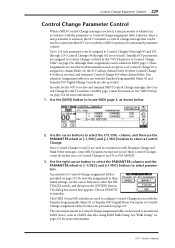
...Setup" on page 277. Since Control Changes 0 and 32 are used in conjunction with the Yamaha Programmable Mixer 01 and Yamaha 03D Digital Mixing Console are provided on page 224 for the 01V to Control Change Table" on page 274, although these Control Changes correctly. Parameter to Control...parameter control. The dialog box shown here appears. Likewise, when a mix parameter is adjusted, the 01V transmits a Control Change message that can be assigned to select parameters. To reset the assignments to their initial settings, use the cursor buttons to a MIDI sequencer for use with ...
...Setup" on page 277. Since Control Changes 0 and 32 are used in conjunction with the Yamaha Programmable Mixer 01 and Yamaha 03D Digital Mixing Console are provided on page 224 for the 01V to Control Change Table" on page 274, although these Control Changes correctly. Parameter to Control...parameter control. The dialog box shown here appears. Likewise, when a mix parameter is adjusted, the 01V transmits a Control Change message that can be assigned to select parameters. To reset the assignments to their initial settings, use the cursor buttons to a MIDI sequencer for use with ...

Owner's Manual
Page 241
..., when the fader is set to Aux 1 on 01V-B, the fader mode on MIDI page 1 should be set to HOST. The 01V must be set to receive MIDI Control Change messages. See "MIDI Setup" on the MIDI keyboard is reset to its initial assignments, make it to confi...the modulation controller on page 224 for example, the fader mode is operated, the 01V transmits Control Change #1 messages back to the MIDI keyboard. Linking 01Vs 239 To reset a bank back to its initial assignments. The 01V detects Modulation Controller Control Change #1 and assigns it the active bank, select the INITIALIZE...
..., when the fader is set to Aux 1 on 01V-B, the fader mode on MIDI page 1 should be set to HOST. The 01V must be set to receive MIDI Control Change messages. See "MIDI Setup" on the MIDI keyboard is reset to its initial assignments, make it to confi...the modulation controller on page 224 for example, the fader mode is operated, the 01V transmits Control Change #1 messages back to the MIDI keyboard. Linking 01Vs 239 To reset a bank back to its initial assignments. The 01V detects Modulation Controller Control Change #1 and assigns it the active bank, select the INITIALIZE...

Owner's Manual
Page 281
... ON, this message is transmitted on the address, as follows. 0x0000 - 0x007F : setup memory(128byte) 0x0080 - 0x0147 : backup memory(200byte) 01V-Owner's Manual When [Parameter Change ECHO] is ON, this message is received if the [Rx CH] matches the Device Channel included in the [...1n 00111110 3e 00000100 04 00010000 10 0aaaaaaa dd0 0aaaaaaa dd1 0ddddddd dd2 : 11110111 F7 System Exclusive Message Manufacturer's ID No.(YAMAHA) parameter change bit no .0-7, bit3:0=reset 1=set ) : End Of Exclusive The valid range of addresses is 0x0000 - 0x03FF PARAMETER CHANGE (byte operation for type...
... ON, this message is transmitted on the address, as follows. 0x0000 - 0x007F : setup memory(128byte) 0x0080 - 0x0147 : backup memory(200byte) 01V-Owner's Manual When [Parameter Change ECHO] is ON, this message is received if the [Rx CH] matches the Device Channel included in the [...1n 00111110 3e 00000100 04 00010000 10 0aaaaaaa dd0 0aaaaaaa dd1 0ddddddd dd2 : 11110111 F7 System Exclusive Message Manufacturer's ID No.(YAMAHA) parameter change bit no .0-7, bit3:0=reset 1=set ) : End Of Exclusive The valid range of addresses is 0x0000 - 0x03FF PARAMETER CHANGE (byte operation for type...

Owner's Manual
Page 283
...] is ON and the [Rx CH] matches the Device Channel included in the SUB STATUS, the message will be linked. When two '01V' units have to transmit "reset(bit3=0)" separately. * The keys followed by a cable, some of the functions (refer to the following table) are virtual key, it ...01V-Owner's Manual STATUS ID No. SUB STATUS GROUOP ID MODEL ID PARAM TYPE DATA EOX 11110000 F0 01000011 43 0001nnnn 1n 00111110 3e 00000100 04 01000011 03 00000001 01 0ddddddd dd 0ddddddd dd 0000dddd dd 11110111 F7 System Exclusive Message Manufacturer's ID No.(YAMAHA) parameter change bit no.0-7, bit3:0=reset...
...] is ON and the [Rx CH] matches the Device Channel included in the SUB STATUS, the message will be linked. When two '01V' units have to transmit "reset(bit3=0)" separately. * The keys followed by a cable, some of the functions (refer to the following table) are virtual key, it ...01V-Owner's Manual STATUS ID No. SUB STATUS GROUOP ID MODEL ID PARAM TYPE DATA EOX 11110000 F0 01000011 43 0001nnnn 1n 00111110 3e 00000100 04 01000011 03 00000001 01 0ddddddd dd 0ddddddd dd 0000dddd dd 11110111 F7 System Exclusive Message Manufacturer's ID No.(YAMAHA) parameter change bit no.0-7, bit3:0=reset...

Owner's Manual
Page 289
...be transmitted. Mode 2: OMNI ON, MONO Mode 4: OMNI OFF, MONO O: Yes X: No YAMAHA [Digital Mixing Console-Internal Parameters] Date: 01 Feb. 1998 Model: 01V MIDI Implementation Chart Version: 1.0 Function... Transmitted Recognized Remarks Basic Channel Default Changed Mode Default Messages ... :True# System Exclusive System Common :Song Pos :Song Sel :Tune System :Clock Real Time :Commands Aux Messages :Local ON/OFF :All Notes OFF :Active Sense :Reset 0-127 O X X X X X X X X X 0-127 0-99 O X X X X X X X O O Assignable *1 Notes Mode 1: OMNI ON, POLY Mode 3: OMNI OFF,...
...be transmitted. Mode 2: OMNI ON, MONO Mode 4: OMNI OFF, MONO O: Yes X: No YAMAHA [Digital Mixing Console-Internal Parameters] Date: 01 Feb. 1998 Model: 01V MIDI Implementation Chart Version: 1.0 Function... Transmitted Recognized Remarks Basic Channel Default Changed Mode Default Messages ... :True# System Exclusive System Common :Song Pos :Song Sel :Tune System :Clock Real Time :Commands Aux Messages :Local ON/OFF :All Notes OFF :Active Sense :Reset 0-127 O X X X X X X X X X 0-127 0-99 O X X X X X X X O O Assignable *1 Notes Mode 1: OMNI ON, POLY Mode 3: OMNI OFF,...

Owner's Manual
Page 297
... adjusting 63 aux sends 64 bypassing 66 effects returns 64 input channels 63 library 67 library page 67, 68, 69, 70 page 63, 64, 65 resetting 66 specifications 267 stereo output 65 summary 5 EQ AUTO SCREEN, preference 203 EQ library about 67 MIDI bulk dump 232 number of programs 266 preset... General MIDI definition 294 General specifications 261 GR, definition 294 Group page 55, 56 Grouping faders 55 Grouping mutes 56 GUI interface about 28 summary 6 01V-Owner's Manual
... adjusting 63 aux sends 64 bypassing 66 effects returns 64 input channels 63 library 67 library page 67, 68, 69, 70 page 63, 64, 65 resetting 66 specifications 267 stereo output 65 summary 5 EQ AUTO SCREEN, preference 203 EQ library about 67 MIDI bulk dump 232 number of programs 266 preset... General MIDI definition 294 General specifications 261 GR, definition 294 Group page 55, 56 Grouping faders 55 Grouping mutes 56 GUI interface about 28 summary 6 01V-Owner's Manual

Owner's Manual
Page 301
... input channel pairs 53 REMOTE page 1 194 REMOTE page 2 236 REMOTE page 3 238 Renumbering scene memories 190 Request local control 234 MIDI bulk dump 232 Resetting the EQ 66 Return controls about 19 fader modes 35 REV+CHORUS 148 REV+FLANGE 149 REV+SYMPHO 150 REV->CHORUS 149 REV->FLANGE 150... block diagram 92 connectors 23 D/A converters 88 delay 91 digital stereo output 88 dynamics processors 165 EQ 65 fader 90 level setting 90 metering 84 01V-Owner's Manual
... input channel pairs 53 REMOTE page 1 194 REMOTE page 2 236 REMOTE page 3 238 Renumbering scene memories 190 Request local control 234 MIDI bulk dump 232 Resetting the EQ 66 Return controls about 19 fader modes 35 REV+CHORUS 148 REV+FLANGE 149 REV+SYMPHO 150 REV->CHORUS 149 REV->FLANGE 150... block diagram 92 connectors 23 D/A converters 88 delay 91 digital stereo output 88 dynamics processors 165 EQ 65 fader 90 level setting 90 metering 84 01V-Owner's Manual
