
Installation Instructions
Page 1
... HOOD COMBINATION SAFETY Your safety and the safety of Contents MICROWAVE HOOD COMBINATION SAFETY 1 INSTALLATION REQUIREMENTS 2 Tools and Parts 2 Remove Cardboard Template 2 Location Requirements 2 Product Dimensions 3 Electrical Requirements 3 INSTALLATION INSTRUCTIONS 4 Remove Mounting Plate 4 Rotate Blower Motor 4 Locate Wall Stud(s 6 Mark Rear Wall 7 Drill Holes in these installation instructions. Always read and...
... HOOD COMBINATION SAFETY Your safety and the safety of Contents MICROWAVE HOOD COMBINATION SAFETY 1 INSTALLATION REQUIREMENTS 2 Tools and Parts 2 Remove Cardboard Template 2 Location Requirements 2 Product Dimensions 3 Electrical Requirements 3 INSTALLATION INSTRUCTIONS 4 Remove Mounting Plate 4 Rotate Blower Motor 4 Locate Wall Stud(s 6 Mark Rear Wall 7 Drill Holes in these installation instructions. Always read and...

Installation Instructions
Page 2
..."Electrical Requirements" section. Special Requirements For Wall Venting Installation Only: ■ Cutout must provide: ■ Minimum installation dimensions. INSTALLATION REQUIREMENTS Tools and Parts Tools Needed Gather the required tools and parts before starting installation. Materials needed ■ Standard... electrical outlet inside the perforation is perforated. Location Requirements Check the opening . ■ Support for use appropriate fasteners. See "Installation Dimensions" illustration. ■ Minimum one 2" x 4" (50.8 x 101.6 mm) wood wall stud and minimum 3/8" (10 mm...
..."Electrical Requirements" section. Special Requirements For Wall Venting Installation Only: ■ Cutout must provide: ■ Minimum installation dimensions. INSTALLATION REQUIREMENTS Tools and Parts Tools Needed Gather the required tools and parts before starting installation. Materials needed ■ Standard... electrical outlet inside the perforation is perforated. Location Requirements Check the opening . ■ Support for use appropriate fasteners. See "Installation Dimensions" illustration. ■ Minimum one 2" x 4" (50.8 x 101.6 mm) wood wall stud and minimum 3/8" (10 mm...

Installation Instructions
Page 3
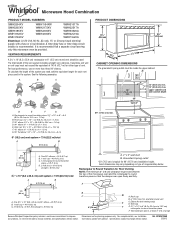
...) min. 14" (35.6 cm) max. Do not use an adapter. Grounded 3 prong outlet *30" (76.2 cm) is properly grounded. Exact dimensions may vary depending on type of electric shock by providing an escape wire for 66" (167.6 cm) installation height. Consult a qualified electrician or serviceman if... having a grounding wire with a fuse or circuit breaker. Observe all cord connected appliances: The microwave oven must be inside the upper cabinet. Product Dimensions 17¹⁄₄" (43.8 cm) 16¹⁄₄" (41.3 cm) (401.05³c⁄₄m") 29⁷⁄₈" ...
...) min. 14" (35.6 cm) max. Do not use an adapter. Grounded 3 prong outlet *30" (76.2 cm) is properly grounded. Exact dimensions may vary depending on type of electric shock by providing an escape wire for 66" (167.6 cm) installation height. Consult a qualified electrician or serviceman if... having a grounding wire with a fuse or circuit breaker. Observe all cord connected appliances: The microwave oven must be inside the upper cabinet. Product Dimensions 17¹⁄₄" (43.8 cm) 16¹⁄₄" (41.3 cm) (401.05³c⁄₄m") 29⁷⁄₈" ...

Installation Instructions
Page 7
Centerline 2. Top of cardboard template must align with the dimensions described in Step 4. See figures 1, 2 and/or 3 in "Possible Wall Stud Configurations" in the shaded areas are ideal hole locations. 7. Using a straightedge, draw the 2 horizontal, ...
Centerline 2. Top of cardboard template must align with the dimensions described in Step 4. See figures 1, 2 and/or 3 in "Possible Wall Stud Configurations" in the shaded areas are ideal hole locations. 7. Using a straightedge, draw the 2 horizontal, ...

Installation Instructions
Page 8
... aligns with the holes in the top of mounting plate, making sure it fits inside the frame, against drywall. 5. Make sure the 10" (25.4 cm) dimension from the back of the mounting plate. Drywall 5. Start toggle nuts on the wall. 2. Securely tighten all contents from the back of the mounting plate...
... aligns with the holes in the top of mounting plate, making sure it fits inside the frame, against drywall. 5. Make sure the 10" (25.4 cm) dimension from the back of the mounting plate. Drywall 5. Start toggle nuts on the wall. 2. Securely tighten all contents from the back of the mounting plate...
Dimension Guide
Page 1
...20 ft (6.1 m) B. 1 wall cap = 40 ft (12.2 m) C. 1 rectangular to improve Dimensions are for each vent piece used . Exact dimensions may vary depending on type of the system you need, add the equivalent length for planning purposes only. ...One 3 " x 10" (8.3 x 25.4 cm) 90° elbow = 25 ft (7.6 m) B. 1 wall cap = 40 ft (12.2 m) C. 2 ft (0.6 m) + 6 ft (1.8 m) straight = 8 ft (2.4 m) B C 3" (7.6 cm) D A. Vent extension piece, at least 3" (7.6 cm) high Because Whirlpool...
...20 ft (6.1 m) B. 1 wall cap = 40 ft (12.2 m) C. 1 rectangular to improve Dimensions are for each vent piece used . Exact dimensions may vary depending on type of the system you need, add the equivalent length for planning purposes only. ...One 3 " x 10" (8.3 x 25.4 cm) 90° elbow = 25 ft (7.6 m) B. 1 wall cap = 40 ft (12.2 m) C. 2 ft (0.6 m) + 6 ft (1.8 m) straight = 8 ft (2.4 m) B C 3" (7.6 cm) D A. Vent extension piece, at least 3" (7.6 cm) high Because Whirlpool...


