Dimension Guide
Page 1
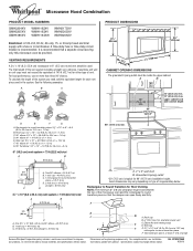
...diameter round vent C. Vent extension piece, at least 3" (7.6 cm) high Because Whirlpool Corporation policy includes a continuous commitment to improve Dimensions are for wall venting only) E D. For complete details, see Installation our products,... A B 6 ft (1.8 m) A. 2" x 4" wall stud B. Elbow (for planning purposes only. Specifications subject to change without notice. ® Microwave Hood Combination PRODUCT MODEL NUMBERS GMH3204XV GMH5205XV GMH6185XV WMH1162XV WMH1163XV WMH1164XW WMH2175XV WMH2205XV WMH3205XV Electrical: A 120-Volt, 60-Hz, AC-only, 15- or 20-amp...
...diameter round vent C. Vent extension piece, at least 3" (7.6 cm) high Because Whirlpool Corporation policy includes a continuous commitment to improve Dimensions are for wall venting only) E D. For complete details, see Installation our products,... A B 6 ft (1.8 m) A. 2" x 4" wall stud B. Elbow (for planning purposes only. Specifications subject to change without notice. ® Microwave Hood Combination PRODUCT MODEL NUMBERS GMH3204XV GMH5205XV GMH6185XV WMH1162XV WMH1163XV WMH1164XW WMH2175XV WMH2205XV WMH3205XV Electrical: A 120-Volt, 60-Hz, AC-only, 15- or 20-amp...

Installation Instructions
Page 1
Table of Contents MICROWAVE HOOD COMBINATION SAFETY 1 INSTALLATION REQUIREMENTS 2 Tools and Parts 2 Remove Cardboard Template 2 Location Requirements 2 Product Dimensions 3 Electrical Requirements 3 INSTALLATION INSTRUCTIONS 4 Remove Mounting Plate 4 Rotate Blower Motor 4 Locate Wall Stud(s...'t immediately follow instructions. W10247296B Always read and obey all safety messages. All safety messages will follow instructions. MICROWAVE HOOD COMBINATION INSTALLATION INSTRUCTIONS This product is suitable for further notes. See "Installation Requirements" section for use above...
Table of Contents MICROWAVE HOOD COMBINATION SAFETY 1 INSTALLATION REQUIREMENTS 2 Tools and Parts 2 Remove Cardboard Template 2 Location Requirements 2 Product Dimensions 3 Electrical Requirements 3 INSTALLATION INSTRUCTIONS 4 Remove Mounting Plate 4 Rotate Blower Motor 4 Locate Wall Stud(s...'t immediately follow instructions. W10247296B Always read and obey all safety messages. All safety messages will follow instructions. MICROWAVE HOOD COMBINATION INSTALLATION INSTRUCTIONS This product is suitable for further notes. See "Installation Requirements" section for use above...

Installation Instructions
Page 2
... x 2" lag screws (2) F. Power supply cord bushing (1) H. Set the cardboard template to the side and refer to back of microwave oven) Cardboard template (part of packaging) Aluminum grease filters Charcoal filters (Depending on model, aluminum grease filter and charcoal filter may not...blade can open freely and fully. Special Requirements For Wall Venting Installation Only: ■ Cutout must provide: ■ Minimum installation dimensions. For Roof Venting Installation Only: ■ If you are for use appropriate fasteners. Sheet metal screws (2) G. Location Requirements ...
... x 2" lag screws (2) F. Power supply cord bushing (1) H. Set the cardboard template to the side and refer to back of microwave oven) Cardboard template (part of packaging) Aluminum grease filters Charcoal filters (Depending on model, aluminum grease filter and charcoal filter may not...blade can open freely and fully. Special Requirements For Wall Venting Installation Only: ■ Cutout must provide: ■ Minimum installation dimensions. For Roof Venting Installation Only: ■ If you are for use appropriate fasteners. Sheet metal screws (2) G. Location Requirements ...

Installation Instructions
Page 3
...: ■ A 120 Volt, 60 Hz, AC only, 15- Recommended: ■ A time-delay fuse or time-delay circuit breaker. ■ A separate circuit serving only this microwave oven. Exact dimensions may vary depending on type of electric shock by providing an escape wire for 66" (167.6 cm) installation height. SAVE THESE INSTRUCTIONS 3 A. 2" x 4" wall stud...
...: ■ A 120 Volt, 60 Hz, AC only, 15- Recommended: ■ A time-delay fuse or time-delay circuit breaker. ■ A separate circuit serving only this microwave oven. Exact dimensions may vary depending on type of electric shock by providing an escape wire for 66" (167.6 cm) installation height. SAVE THESE INSTRUCTIONS 3 A. 2" x 4" wall stud...

Installation Instructions
Page 7
Mark Rear Wall The microwave oven must be installed on a minimum of 1 wall stud, preferably 2, using a minimum of the upper cabinet. 9. D. These represent the mounting plate's end holes and bottom ... the bottom edge of the upper cabinet, and must each other. if 1 end hole is damaged or unusable, measure and mark the wall with the dimensions described in one 1/4-20 x 3" round-head bolt with toggle nuts; or if both end holes marked in steps 8 and 10. 12. Installation for No Wall...
Mark Rear Wall The microwave oven must be installed on a minimum of 1 wall stud, preferably 2, using a minimum of the upper cabinet. 9. D. These represent the mounting plate's end holes and bottom ... the bottom edge of the upper cabinet, and must each other. if 1 end hole is damaged or unusable, measure and mark the wall with the dimensions described in one 1/4-20 x 3" round-head bolt with toggle nuts; or if both end holes marked in steps 8 and 10. 12. Installation for No Wall...

Installation Instructions
Page 8
... the bolts to the thickest part of the rear wall (for Wall Stud at One End Hole" in the "Drill Holes in Step 2 of the microwave oven. With the support tabs of the mounting plate facing forward, insert a 1/4-20 x 3" round-head bolt through both end holes. 3. Check alignment of ... either 1/4-20 x 3" round-head bolts and toggle nuts or 1/4 x 2" lag screws. Check alignment of the mounting plate. Make sure the 10" (25.4 cm) dimension from the back of mounting plate, making sure it is level. 7. Securely tighten all contents from the back of mounting plate, making sure it is...
... the bolts to the thickest part of the rear wall (for Wall Stud at One End Hole" in the "Drill Holes in Step 2 of the microwave oven. With the support tabs of the mounting plate facing forward, insert a 1/4-20 x 3" round-head bolt through both end holes. 3. Check alignment of ... either 1/4-20 x 3" round-head bolts and toggle nuts or 1/4 x 2" lag screws. Check alignment of the mounting plate. Make sure the 10" (25.4 cm) dimension from the back of mounting plate, making sure it is level. 7. Securely tighten all contents from the back of mounting plate, making sure it is...


