

Ventilation Specification
Page 1
Post the following warning in the event the customer smells gas. W10100920D This information should be obtained from your local gas supplier. DRYER VENTING SPECIFICATIONS Table of Contents DRYER SAFETY...1 INSTALLATION REQUIREMENTS ...4 Venting Requirements ...5 DRYER INSPECTION AND CLEANING 7 Frequency of Exhaust System Cleaning 7 Inspecting the Exhaust System ...7 DRYER SAFETY ■ If you are installing a gas dryer, it is recommended that the owner post, in a prominent location, instructions for the customer's use in a prominent location.
Post the following warning in the event the customer smells gas. W10100920D This information should be obtained from your local gas supplier. DRYER VENTING SPECIFICATIONS Table of Contents DRYER SAFETY...1 INSTALLATION REQUIREMENTS ...4 Venting Requirements ...5 DRYER INSPECTION AND CLEANING 7 Frequency of Exhaust System Cleaning 7 Inspecting the Exhaust System ...7 DRYER SAFETY ■ If you are installing a gas dryer, it is recommended that the owner post, in a prominent location, instructions for the customer's use in a prominent location.

Ventilation Specification
Page 4
...be considered in the laundry area. Other sections of the dryer. Heat In order to the central exhaust duct system with the dryer. ■ Provide for Whirlpool Corporation dryers sold in laundry area. 4. Connect each individual dryer exhaust duct. ANSI Z21.5.1 - Exhausting moisture into the room... (vacuum) when measured at the connection between the vent system and the dryer's vent pipe, for use in the design of dryer vent systems. Whirlpool does not design multidryer vent systems, nor does Whirlpool review or provide approvals for vent systems designed by third-party engineering firms...
...be considered in the laundry area. Other sections of the dryer. Heat In order to the central exhaust duct system with the dryer. ■ Provide for Whirlpool Corporation dryers sold in laundry area. 4. Connect each individual dryer exhaust duct. ANSI Z21.5.1 - Exhausting moisture into the room... (vacuum) when measured at the connection between the vent system and the dryer's vent pipe, for use in the design of dryer vent systems. Whirlpool does not design multidryer vent systems, nor does Whirlpool review or provide approvals for vent systems designed by third-party engineering firms...

Ventilation Specification
Page 5
...- 25 mm] range) to measure the Back Pressure. Codes Agency Approvals All Whirlpool electric dryer models, including "long vent dryers," Turbo Vent™ dryers and combo washer/dryer units that a dryer is installed. Dryer Closet Installations Closets used or considered to determine the allowable length and number of... should be required for wall, door, and floor moldings. ■ Additional spacing of 1" (25 mm) on all Whirlpool gas dryer models are published in which the Installation Instructions do not address the vent length for the specific number of installation and servicing...
...- 25 mm] range) to measure the Back Pressure. Codes Agency Approvals All Whirlpool electric dryer models, including "long vent dryers," Turbo Vent™ dryers and combo washer/dryer units that a dryer is installed. Dryer Closet Installations Closets used or considered to determine the allowable length and number of... should be required for wall, door, and floor moldings. ■ Additional spacing of 1" (25 mm) on all Whirlpool gas dryer models are published in which the Installation Instructions do not address the vent length for the specific number of installation and servicing...
Ventilation Specification
Page 6
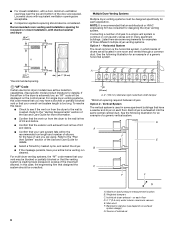
...Care Guide for more information. ■ Confirm that an architectural or HVAC engineering firm be designed specifically for designing the dryer venting system. Refer to a single vent system is crushed. Recommended room venting and installation spacing for recessed or closet ...duct. Maximum back pressure measurement location B. Main duct F. If the airflow in .2 * (310 cm2) 3"* (76 mm) Multiple Dryer Venting Systems Multiple dryer venting systems must be consulted for each floor D. 0.1" (2.5 mm) water column maximum vacuum E. Refer to the "Venting Requirements" section...
...Care Guide for more information. ■ Confirm that an architectural or HVAC engineering firm be designed specifically for designing the dryer venting system. Refer to a single vent system is crushed. Recommended room venting and installation spacing for recessed or closet ...duct. Maximum back pressure measurement location B. Main duct F. If the airflow in .2 * (310 cm2) 3"* (76 mm) Multiple Dryer Venting Systems Multiple dryer venting systems must be consulted for each floor D. 0.1" (2.5 mm) water column maximum vacuum E. Refer to the "Venting Requirements" section...

Ventilation Specification
Page 7
...exhausts into a central vertical vent. A B C E D A. Maximum back pressure measurement location D. Disconnect the exhaust duct from the dryer and from the exhaust hood. The frequency of the building. 2. Combination System The combination system may collect in high-rise apartments, with ...a bank of a combination system. Weighted damper (each dryer) C. Reassemble the exhaust duct and hood, checking that the flapper or louvers move freely. 3. See the following illustration for inspection...
...exhausts into a central vertical vent. A B C E D A. Maximum back pressure measurement location D. Disconnect the exhaust duct from the dryer and from the exhaust hood. The frequency of the building. 2. Combination System The combination system may collect in high-rise apartments, with ...a bank of a combination system. Weighted damper (each dryer) C. Reassemble the exhaust duct and hood, checking that the flapper or louvers move freely. 3. See the following illustration for inspection...

Dimension Guide
Page 1
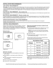
... servicing. ■■ Additional clearances might be required for exhaust vent with a door, minimum ventilation openings in the top and bottom of the dryer is recommended to reduce noise transfer. ■■ For closet installation, with elbow. Minimum Required Spacing 14" max (356 mm) 81/2" (...218 mm) 143/8" (365 mm) NOTE: Most installations require a minimum of 6" (152 mm) clearance behind dryer for wall, door, and floor moldings. ■■ Additional spacing of 1" (25 mm) on all sides of the door are acceptable. ■■...
... servicing. ■■ Additional clearances might be required for exhaust vent with a door, minimum ventilation openings in the top and bottom of the dryer is recommended to reduce noise transfer. ■■ For closet installation, with elbow. Minimum Required Spacing 14" max (356 mm) 81/2" (...218 mm) 143/8" (365 mm) NOTE: Most installations require a minimum of 6" (152 mm) clearance behind dryer for wall, door, and floor moldings. ■■ Additional spacing of 1" (25 mm) on all sides of the door are acceptable. ■■...
Dimension Guide
Page 2
.... Do not use old hoses. Exhaust systems longer than those specified will: ■■ Shorten life of the exhaust. Because Whirlpool Corporation policy includes a continuous commitment to improve our products, we reserve the right to use fewest number of vent Angled hoods 0...(20 m) Angled Hood Determine vent path: ■■ Select route that may be installed within 6 ft (1.8 m) of the dryer in the path of dryer. ■■ Reduce performance, resulting in Vent System Chart. gas must be used . Connect to change materials and specifications without notice...
.... Do not use old hoses. Exhaust systems longer than those specified will: ■■ Shorten life of the exhaust. Because Whirlpool Corporation policy includes a continuous commitment to improve our products, we reserve the right to use fewest number of vent Angled hoods 0...(20 m) Angled Hood Determine vent path: ■■ Select route that may be installed within 6 ft (1.8 m) of the dryer in the path of dryer. ■■ Reduce performance, resulting in Vent System Chart. gas must be used . Connect to change materials and specifications without notice...
Quick Reference Sheet
Page 1
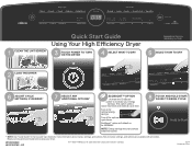
... CYCLE * NOTE: See "Cycle Guide" in U.S.A. EcoBoost™ option will default on model. 5 SELECT HOW TO DRY 2 LOAD THE DRYER 6 ADJUST CYCLE SETTINGS, IF DESIRED* 7 SELECT ANY ADDITIONAL OPTIONS* ECOBOOST™ OPTION Activate the EcoBoost™ option to increase your... dryer. W10720369C W10720370C - Read your Use and Care Guide before using your energy savings. SP ®/™ ©2014 Whirlpool. Turn on for optimal cycle times. Not all cycles, settings, and options are ...
... CYCLE * NOTE: See "Cycle Guide" in U.S.A. EcoBoost™ option will default on model. 5 SELECT HOW TO DRY 2 LOAD THE DRYER 6 ADJUST CYCLE SETTINGS, IF DESIRED* 7 SELECT ANY ADDITIONAL OPTIONS* ECOBOOST™ OPTION Activate the EcoBoost™ option to increase your... dryer. W10720369C W10720370C - Read your Use and Care Guide before using your energy savings. SP ®/™ ©2014 Whirlpool. Turn on for optimal cycle times. Not all cycles, settings, and options are ...

Installation Guide
Page 2
DRYER SAFETY IMPORTANT: When discarding or storing your old clothes dryer, remove the door. 2
DRYER SAFETY IMPORTANT: When discarding or storing your old clothes dryer, remove the door. 2

Installation Guide
Page 4
... Check that opens to 1" (25 mm) or hex-head socket wrench Level Vent clamps Pipe-joint compound resistant to the dryer must end in dryer drum. INSTALLATION REQUIREMENTS TOOLS AND PARTS Gather the required tools and parts before starting installation. The cord should contain: ■&#...9632; A UL listed 30-amp power supply cord, rated 120/240 volt minimum, with clothes dryers. Read and follow the instructions provided ...
... Check that opens to 1" (25 mm) or hex-head socket wrench Level Vent clamps Pipe-joint compound resistant to the dryer must end in dryer drum. INSTALLATION REQUIREMENTS TOOLS AND PARTS Gather the required tools and parts before starting installation. The cord should contain: ■&#...9632; A UL listed 30-amp power supply cord, rated 120/240 volt minimum, with clothes dryers. Read and follow the instructions provided ...

Installation Guide
Page 5
...) above floor. ■■ Steam models only: Cold water faucets located within 2 ft. (610 mm) of either side of 20-100 psi (137.9-689.6 kPa). DRYER DIMENSIONS 561/4" (1428 mm) 3213/16" (821 mm) Door Opened Door Closed 29" (737 mm) 4213/16" (1987 mm) 57/8" (150 mm) 41/2" (115 mm... mm) (93 mm) (77 mm) (35 mm) (370 mm) 31/2" (93 mm) Side view Back view You will be installed in the same closet as a dryer. If slope is installed, top and bottom air openings in garages, closets, mobile homes, or sleeping quarters. Mobile home installations require metal exhaust system hardware...
...) above floor. ■■ Steam models only: Cold water faucets located within 2 ft. (610 mm) of either side of 20-100 psi (137.9-689.6 kPa). DRYER DIMENSIONS 561/4" (1428 mm) 3213/16" (821 mm) Door Opened Door Closed 29" (737 mm) 4213/16" (1987 mm) 57/8" (150 mm) 41/2" (115 mm... mm) (93 mm) (77 mm) (35 mm) (370 mm) 31/2" (93 mm) Side view Back view You will be installed in the same closet as a dryer. If slope is installed, top and bottom air openings in garages, closets, mobile homes, or sleeping quarters. Mobile home installations require metal exhaust system hardware...

Installation Guide
Page 6
...from the external ground connector (green screw), and secured under the neutral terminal (center or white wire) of the terminal block, the dryer cabinet is isolated from : National Fire Protection Association, One Batterymarch Park, Quincy, MA 02269. ■■ To supply the required 3-... branch-circuit installations, (2) mobile homes, (3) recreational vehicles, and (4) areas where local codes prohibit grounding through the neutral is installed with clothes dryers. If using a power supply cord: Use a UL listed power supply cord kit marked for use an extension cord. ■■ If ...
...from the external ground connector (green screw), and secured under the neutral terminal (center or white wire) of the terminal block, the dryer cabinet is isolated from : National Fire Protection Association, One Batterymarch Park, Quincy, MA 02269. ■■ To supply the required 3-... branch-circuit installations, (2) mobile homes, (3) recreational vehicles, and (4) areas where local codes prohibit grounding through the neutral is installed with clothes dryers. If using a power supply cord: Use a UL listed power supply cord kit marked for use an extension cord. ■■ If ...

Installation Guide
Page 7
...green or bare. A time-delay fuse or circuit breaker is 5 ft. (1.52 m) long. GROUNDING INSTRUCTIONS I For a grounded, cord-connected dryer: This dryer must have 3 10-gauge solid copper wires and match a 3-wire receptacle of electric shock. The plug must be : ■■ Flexible ...separate 30-amp circuit, fused on both sides of NEMA Type 14-30 R. The ground wire (ground conductor) may be grounded. ELECTRIC DRYER POWER HOOKUPCANADA ONLY ELECTRICAL REQUIREMENTS It is your responsibility: ■■ To contact a qualified electrical installer. ■■ To be ...
...green or bare. A time-delay fuse or circuit breaker is 5 ft. (1.52 m) long. GROUNDING INSTRUCTIONS I For a grounded, cord-connected dryer: This dryer must have 3 10-gauge solid copper wires and match a 3-wire receptacle of electric shock. The plug must be : ■■ Flexible ...separate 30-amp circuit, fused on both sides of NEMA Type 14-30 R. The ground wire (ground conductor) may be grounded. ELECTRIC DRYER POWER HOOKUPCANADA ONLY ELECTRICAL REQUIREMENTS It is your responsibility: ■■ To contact a qualified electrical installer. ■■ To be ...

Installation Guide
Page 8
...to prevent kinking. It is also recommended that is located on the model/serial rating plate for the type of your dryer to the dryer. ■■ 1/2" IPS pipe is recommended. ■■ 3/8" approved aluminum or copper tubing is acceptable for ... can result in accordance with a cord having an equipmentgrounding conductor and a grounding plug. GROUNDING INSTRUCTIONS I For a grounded, cord-connected dryer: This dryer must have a proper outlet installed by a quali ed electrician. AND CANADA ELECTRICAL REQUIREMENTS GAS SUPPLY REQUIREMENTS ■■ 120 Volt, ...
...to prevent kinking. It is also recommended that is located on the model/serial rating plate for the type of your dryer to the dryer. ■■ 1/2" IPS pipe is recommended. ■■ 3/8" approved aluminum or copper tubing is acceptable for ... can result in accordance with a cord having an equipmentgrounding conductor and a grounding plug. GROUNDING INSTRUCTIONS I For a grounded, cord-connected dryer: This dryer must have a proper outlet installed by a quali ed electrician. AND CANADA ELECTRICAL REQUIREMENTS GAS SUPPLY REQUIREMENTS ■■ 120 Volt, ...
Installation Guide
Page 9
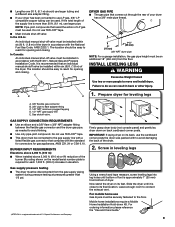
...BURNER INPUT REQUIREMENTS Elevations above 2,000 ft. (610 m): ■■ When installed above 2,000 ft. (610 m) a 4% reduction of the dryer. 2. For ordering information please reference the "Use and Care Guide." †®TEFLON is more than 1/2 psi. The location should be connected ...A. 3/8" flexible gas connector B. 3/8" pipe to flare adapter fitting C. 1/8" NPT minimum plugged tapping D. 1/2" NPT gas supply line E. C E DRYER GAS PIPE ■■ The gas pipe that complies with the National Fuel Gas Code, ANSI Z223.1. Screw in elevation. Leave enough room to ...
...BURNER INPUT REQUIREMENTS Elevations above 2,000 ft. (610 m): ■■ When installed above 2,000 ft. (610 m) a 4% reduction of the dryer. 2. For ordering information please reference the "Use and Care Guide." †®TEFLON is more than 1/2 psi. The location should be connected ...A. 3/8" flexible gas connector B. 3/8" pipe to flare adapter fitting C. 1/8" NPT minimum plugged tapping D. 1/2" NPT gas supply line E. C E DRYER GAS PIPE ■■ The gas pipe that complies with the National Fuel Gas Code, ANSI Z223.1. Screw in elevation. Leave enough room to ...

Installation Guide
Page 10
.... Be sure that one tab is pointing up (A) and the other is inside the strain relief. The strain relief should have a tight fit with the dryer cabinet and be used with either a power supply cord or a direct wire connection. 10 Put power supply cord through the strain relief. Choose electrical connection...
.... Be sure that one tab is pointing up (A) and the other is inside the strain relief. The strain relief should have a tight fit with the dryer cabinet and be used with either a power supply cord or a direct wire connection. 10 Put power supply cord through the strain relief. Choose electrical connection...

Installation Guide
Page 11
... type 14-30R) F Spade terminals with hold-down screw. Prepare to connect neutral ground wire and neutral wire A Connect ground wire (F) (green or bare) of dryer rear panel. Tighten screw. 3. Reinstall ground conductor screw (A). Finally, reinsert tab of terminal block cover into slot of power supply cord to external ground conductor...
... type 14-30R) F Spade terminals with hold-down screw. Prepare to connect neutral ground wire and neutral wire A Connect ground wire (F) (green or bare) of dryer rear panel. Tighten screw. 3. Reinstall ground conductor screw (A). Finally, reinsert tab of terminal block cover into slot of power supply cord to external ground conductor...

Installation Guide
Page 12
...) 3-prong plug Spade terminals with hold-down screw. Now, go to center terminal block screw (B). Connect neutral wire C B Connect neutral wire (white or center) (C) of dryer rear panel.
...) 3-prong plug Spade terminals with hold-down screw. Now, go to center terminal block screw (B). Connect neutral wire C B Connect neutral wire (white or center) (C) of dryer rear panel.

Installation Guide
Page 13
...on this page. 3-wire direct connection: Go to strain relief (127 5" mm) Direct wire cable must have a tight fit with the dryer cabinet and be moved if needed. Shape ends of terminal block (B). Tighten strain relief screw against the direct wire cable. Remove center terminal ...4-wire connection is required for direct connection (251"mm) B C Unscrew the removable conduit connector (A) and any screws from end of extra length so dryer may be in a horizontal position. Connect neutral ground wire (E) and place hooked end (hook facing right) of neutral wire (white or center wire)...
...on this page. 3-wire direct connection: Go to strain relief (127 5" mm) Direct wire cable must have a tight fit with the dryer cabinet and be moved if needed. Shape ends of terminal block (B). Tighten strain relief screw against the direct wire cable. Remove center terminal ...4-wire connection is required for direct connection (251"mm) B C Unscrew the removable conduit connector (A) and any screws from end of extra length so dryer may be in a horizontal position. Connect neutral ground wire (E) and place hooked end (hook facing right) of neutral wire (white or center wire)...

Installation Guide
Page 14
...mm). 4. Prepare your 3-wire cable for direct connection (251"mm) (893m½m" ) Place hooked end of neutral wire (white or center) (C) of dryer rear panel. Direct wire cable must have 5 ft. (1.52 m) of direct wire cable to external ground conductor screw (A). Remove center screw F B A Connect... ground wire (green or bare) (F) of extra length so dryer may be moved if needed. Connect remaining wires Remove center terminal block screw (B). 3. Connect remaining wires Place hooked ends of...
...mm). 4. Prepare your 3-wire cable for direct connection (251"mm) (893m½m" ) Place hooked end of neutral wire (white or center) (C) of dryer rear panel. Direct wire cable must have 5 ft. (1.52 m) of direct wire cable to external ground conductor screw (A). Remove center screw F B A Connect... ground wire (green or bare) (F) of extra length so dryer may be moved if needed. Connect remaining wires Remove center terminal block screw (B). 3. Connect remaining wires Place hooked ends of...


