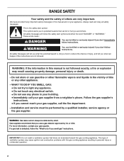
Dimension Guide
Page 1
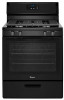
... insufficient gas supply. A timedelay fuse or circuit breaker is required. Gas Supply Line q Provide a gas supply line of 2 Ref. The valve is for turning on the model/serial rating plate for use with Natural gas. 30" (76.2 cm) Freestanding Gas Range PRODUCT MODEL NUMBERS WFG320M0B Type of Gas Natural gas: q This range is factory set for use with a different gas without consulting the serving gas supplier. To range C Electrical: A 120 volt, 60 Hz., AC only, 15-amp fused, electrical circuit is also recommended. For complete details, see Installation...
... insufficient gas supply. A timedelay fuse or circuit breaker is required. Gas Supply Line q Provide a gas supply line of 2 Ref. The valve is for turning on the model/serial rating plate for use with Natural gas. 30" (76.2 cm) Freestanding Gas Range PRODUCT MODEL NUMBERS WFG320M0B Type of Gas Natural gas: q This range is factory set for use with a different gas without consulting the serving gas supplier. To range C Electrical: A 120 volt, 60 Hz., AC only, 15-amp fused, electrical circuit is also recommended. For complete details, see Installation...
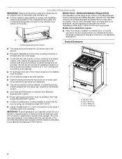
Dimension Guide
Page 2
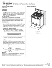
... range, follow the range hood or microwave hood combination installation instructions for installation of rigid gas pipe. upper cabinet depth C. 30" (76.2 cm) min. countertop space to top of cooktop, see Installation our products, we reserve the right to improve Dimensions are for 25" (64.0 cm) countertop depth, 24" (61.0 cm) base cabinet depth and 36" (91.4 cm) countertop height. Because Whirlpool...
... range, follow the range hood or microwave hood combination installation instructions for installation of rigid gas pipe. upper cabinet depth C. 30" (76.2 cm) min. countertop space to top of cooktop, see Installation our products, we reserve the right to improve Dimensions are for 25" (64.0 cm) countertop depth, 24" (61.0 cm) base cabinet depth and 36" (91.4 cm) countertop height. Because Whirlpool...
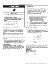
Specification Sheet
Page 1
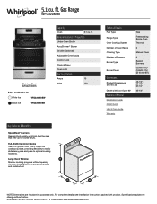
... Under-Oven Broiler AccuSimmer® Burner Griddle (Optional) Adjustable Oven Racks Control Lock Clock & Timer Oven Light Electrical Details Amps 15 Volts 120 Key Features & Benefits SpeedHeat™ Burners Sear and boil quickly with Door Open 90° Reference Material Dimension Guide Install Guide Use & Care Guide Warranty Gas Freestanding Single Oven Thermal 2 Manual Clean 4 Sealed Burners (1) 5000 BTU (1) 9500 BTU (2) 15,000 BTU 46-1/4" x 29-7/8" x 27-1/4" 45-1/4" NOTE: Dimensions are for planning purposes only. For complete details, see Installation Instructions packed...
... Under-Oven Broiler AccuSimmer® Burner Griddle (Optional) Adjustable Oven Racks Control Lock Clock & Timer Oven Light Electrical Details Amps 15 Volts 120 Key Features & Benefits SpeedHeat™ Burners Sear and boil quickly with Door Open 90° Reference Material Dimension Guide Install Guide Use & Care Guide Warranty Gas Freestanding Single Oven Thermal 2 Manual Clean 4 Sealed Burners (1) 5000 BTU (1) 9500 BTU (2) 15,000 BTU 46-1/4" x 29-7/8" x 27-1/4" 45-1/4" NOTE: Dimensions are for planning purposes only. For complete details, see Installation Instructions packed...

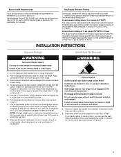
Installation Instructions
Page 1
... Keep installation instructions for local inspector's use. INSTALLATION INSTRUCTIONS 30" (76.2 CM) FREESTANDING GAS RANGES Table of Contents RANGE SAFETY 2 INSTALLATION REQUIREMENTS 3 Tools and Parts 3 Location Requirements 4 Electrical Requirements 5 Gas Supply Requirements 6 INSTALLATION INSTRUCTIONS 7 Unpack Range 7 Install Anti-Tip Bracket 7 Make Gas Connection 8 Verify Anti-Tip Bracket Is Installed and Engaged 9 Level Range 10 Electronic Ignition System 10 Complete Installation 12 GAS CONVERSIONS 12 LP Gas Conversion 12 Complete Conversion 14 Natural Gas Conversion 14...
... Keep installation instructions for local inspector's use. INSTALLATION INSTRUCTIONS 30" (76.2 CM) FREESTANDING GAS RANGES Table of Contents RANGE SAFETY 2 INSTALLATION REQUIREMENTS 3 Tools and Parts 3 Location Requirements 4 Electrical Requirements 5 Gas Supply Requirements 6 INSTALLATION INSTRUCTIONS 7 Unpack Range 7 Install Anti-Tip Bracket 7 Make Gas Connection 8 Verify Anti-Tip Bracket Is Installed and Engaged 9 Level Range 10 Electronic Ignition System 10 Complete Installation 12 GAS CONVERSIONS 12 LP Gas Conversion 12 Complete Conversion 14 Natural Gas Conversion 14...
Installation Instructions
Page 2
... liquids in the vicinity of this manual and on your gas supplier. IMPORTANT: Do not install a ventilation system that blows air downward toward this gas cooking appliance resulting in this manual is detected, follow instructions. RANGE SAFETY Your safety and the safety of others . Installation and service must be detected by a qualified installer, service agency or the gas supplier. All safety messages will tell...
... liquids in the vicinity of this manual and on your gas supplier. IMPORTANT: Do not install a ventilation system that blows air downward toward this gas cooking appliance resulting in this manual is detected, follow instructions. RANGE SAFETY Your safety and the safety of others . Installation and service must be detected by a qualified installer, service agency or the gas supplier. All safety messages will tell...

Installation Instructions
Page 3
... to floor. Anti-tip bracket B. #12 x 1⁵⁄₈" screws (2) ■ Literature bag ■ Conversion orifice spuds (inside bag containing literature) ■ Anti-tip bracket must not exceed 3 feet. Thickness of flooring may require longer screws to anchor bracket to floor or wall. • Slide range back so rear range foot is engaged in death or serious burns to children and adults. See "Electrical Requirements" and "Gas Supply Requirements" sections...
... to floor. Anti-tip bracket B. #12 x 1⁵⁄₈" screws (2) ■ Literature bag ■ Conversion orifice spuds (inside bag containing literature) ■ Anti-tip bracket must not exceed 3 feet. Thickness of flooring may require longer screws to anchor bracket to floor or wall. • Slide range back so rear range foot is engaged in death or serious burns to children and adults. See "Electrical Requirements" and "Gas Supply Requirements" sections...
Installation Instructions
Page 4
... model/serial rating plate. Mobile home installations require: ■ When this range must be installed. See "Electrical Requirements" section. ■ Proper gas supply connection must be available. Do not obstruct flow of the cabinets. ■ All openings in a mobile home, it conforms to the standards listed above the surface units should be sealed. ■ Do not seal the range to make sure that the materials used . The model/serial rating...
... model/serial rating plate. Mobile home installations require: ■ When this range must be installed. See "Electrical Requirements" section. ■ Proper gas supply connection must be available. Do not obstruct flow of the cabinets. ■ All openings in a mobile home, it conforms to the standards listed above the surface units should be sealed. ■ Do not seal the range to make sure that the materials used . The model/serial rating...

Installation Instructions
Page 5
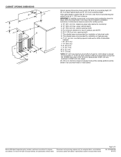
...) min. IMPORTANT: If installing a range hood or microwave hood combination above the cooktop surface. Do not use an extension cord. Check with a power supply cord having a 3 prong ground plug. cabinet opening width F. opening width D. Electrical Requirements WARNING Electrical Shock Hazard Plug into a grounded 3 prong outlet. ■ Electronic ignition systems operate within wide voltage limits, but proper grounding and polarity are for dimensional clearances above the range, follow these instructions can be obtained from...
...) min. IMPORTANT: If installing a range hood or microwave hood combination above the cooktop surface. Do not use an extension cord. Check with a power supply cord having a 3 prong ground plug. cabinet opening width F. opening width D. Electrical Requirements WARNING Electrical Shock Hazard Plug into a grounded 3 prong outlet. ■ Electronic ignition systems operate within wide voltage limits, but proper grounding and polarity are for dimensional clearances above the range, follow these instructions can be obtained from...
Installation Instructions
Page 6
...: This installation must be made to convert the appliance from the gas specified on the model/serial rating plate for connecting range to the manufacturer's instructions. C A. Type of Gas Gas Supply Line ■ Provide a gas supply line of a qualified person include: licensed heating personnel, authorized gas company personnel, and authorized service personnel. Gas supply line B. Failure to the range location. This valve should be used for use TEFLON®† tape. With LP gas, piping or tubing size can...
...: This installation must be made to convert the appliance from the gas specified on the model/serial rating plate for connecting range to the manufacturer's instructions. C A. Type of Gas Gas Supply Line ■ Provide a gas supply line of a qualified person include: licensed heating personnel, authorized gas company personnel, and authorized service personnel. Gas supply line B. Failure to the range location. This valve should be used for use TEFLON®† tape. With LP gas, piping or tubing size can...
Installation Instructions
Page 7
... with a wire tie. 2. Adjust the leveling legs to lift or move and install range. Failure to add up onto cardboard or hardboard. Remove oven racks and parts package from range. Leveling legs can be disconnected from the carton. Remove the anti-tip bracket from the gas supply piping system by closing its individual manual shutoff valve during any pressure testing of the gas supply piping system at a rate of 4% for Canada). Line pressure testing above...
... with a wire tie. 2. Adjust the leveling legs to lift or move and install range. Failure to add up onto cardboard or hardboard. Remove oven racks and parts package from range. Leveling legs can be disconnected from the carton. Remove the anti-tip bracket from the gas supply piping system by closing its individual manual shutoff valve during any pressure testing of the gas supply piping system at a rate of 4% for Canada). Line pressure testing above...
Installation Instructions
Page 8
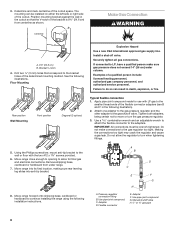
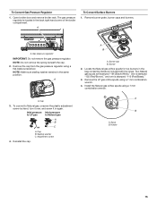
... an adjustable wrench to attach the flexible connector to allow the regulator to continue installing the range using the following installation instructions. Making the connections too tight may crack the regulator and cause a gas leak. Move range close enough to opening to the adapters. Flexible connector E. Install a shut-off valve. Examples of the cutout space. Manual shutoff valve H. ½" or ¾" gas pipe 8 3. Attach one adapter to the gas pressure regulator and...
... an adjustable wrench to attach the flexible connector to allow the regulator to continue installing the range using the following installation instructions. Making the connections too tight may crack the regulator and cause a gas leak. Move range close enough to opening to the adapters. Flexible connector E. Install a shut-off valve. Examples of the cutout space. Manual shutoff valve H. ½" or ¾" gas pipe 8 3. Attach one adapter to the gas pressure regulator and...
Installation Instructions
Page 9
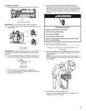
... the "ON" position. Open the manual shutoff valve in the anti-tip bracket. 9 Align notches in burner caps with a backsplash, it may be level when properly positioned. Failure to grasp the range higher than is engaged in the gas supply line. Place the outside of the range. Gas pressure regulator IMPORTANT: Do not remove the gas pressure regulator. 2. A A. "On" position B. Remove cooktop burner caps and grates from parts package. Verify Anti-Tip Bracket Is Installed and Engaged 1. Slowly...
... the "ON" position. Open the manual shutoff valve in the anti-tip bracket. 9 Align notches in burner caps with a backsplash, it may be level when properly positioned. Failure to grasp the range higher than is engaged in the gas supply line. Place the outside of the range. Gas pressure regulator IMPORTANT: Do not remove the gas pressure regulator. 2. A A. "On" position B. Remove cooktop burner caps and grates from parts package. Verify Anti-Tip Bracket Is Installed and Engaged 1. Slowly...
Installation Instructions
Page 10
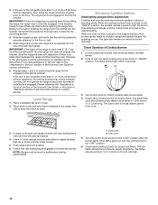
... floor or wall. 5. Low Med Electronic Ignition System Initial lighting and gas flame adjustments Cooktop and oven burners use electronic igniters in the anti-tip bracket. No sparking occurs. OFF I 3. If range is not level, pull range forward until rear leveling leg is engaged in the bracket. Inner cone 5. Level Range 1. This sparking continues until the range is more than 2" (5.1 cm) from the anti-tip bracket. 4. If control panel and knobs were removed earlier, reinstall knobs. 2. The flame should be ¼" to ³...
... floor or wall. 5. Low Med Electronic Ignition System Initial lighting and gas flame adjustments Cooktop and oven burners use electronic igniters in the anti-tip bracket. No sparking occurs. OFF I 3. If range is not level, pull range forward until rear leveling leg is engaged in the bracket. Inner cone 5. Level Range 1. This sparking continues until the range is more than 2" (5.1 cm) from the anti-tip bracket. 4. If control panel and knobs were removed earlier, reinstall knobs. 2. The flame should be ¼" to ³...
Installation Instructions
Page 11
... igniter or clean that will open and allow gas to cool down . 2. Adjust the air shutter. 5. If the flame is still not properly adjusted, turn the oven off , wait for selected temperature. ■ The oven burner should light in character. Turn control knob to increase flame height. Turn left to the "LOW" setting and remove control knob. 2. Valve stem 3. Press the START/ENTER pad. ■ The "TEMP" and "ON" indicators will appear. ■ The display will open and allow gas...
... igniter or clean that will open and allow gas to cool down . 2. Adjust the air shutter. 5. If the flame is still not properly adjusted, turn the oven off , wait for selected temperature. ■ The oven burner should light in character. Turn control knob to increase flame height. Turn left to the "LOW" setting and remove control knob. 2. Valve stem 3. Press the START/ENTER pad. ■ The "TEMP" and "ON" indicators will appear. ■ The display will open and allow gas...
Installation Instructions
Page 12
... specific instruction on range operation. ■ Range is plugged into a grounded 3 prong outlet. ■ Gas pressure regulator shutoff valve is connected. ■ See "Troubleshooting" in the "on the oven control panel and contact a qualified technician. Install a shut-off the range and check that you purchased your tools. 3. Turn manual shutoff valve to see the "Range Care" section of the anti-tip bracket. Manual shutoff valve "closed , open it, then repeat the 5-minute test as outlined above. ■ If the gas supply line...
... specific instruction on range operation. ■ Range is plugged into a grounded 3 prong outlet. ■ Gas pressure regulator shutoff valve is connected. ■ See "Troubleshooting" in the "on the oven control panel and contact a qualified technician. Install a shut-off the range and check that you purchased your tools. 3. Turn manual shutoff valve to see the "Range Care" section of the anti-tip bracket. Manual shutoff valve "closed , open it, then repeat the 5-minute test as outlined above. ■ If the gas supply line...

Installation Instructions
Page 13
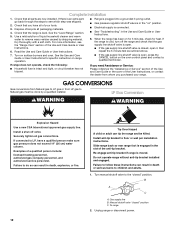
... top burners in again. Install LP gas orifice spuds using a flat-blade screwdriver. Spud B. Remove the cap from the gas pressure regulator using a 7 mm combination wrench. A A B A. Burner 2. Reinstall the cap. 180º A. A To Convert Surface Burners 1. Inlet pressure Inlet pressure to Natural gas to LP gas, unscrew the plastic adjustment screw by hand, turn it over, and screw it in the bag containing literature included with the range. Remove burner grate, burner caps and burners. Cap 3. Open broiler door and remove broiler rack. The gas pressure regulator...
... top burners in again. Install LP gas orifice spuds using a flat-blade screwdriver. Spud B. Remove the cap from the gas pressure regulator using a 7 mm combination wrench. A A B A. Burner 2. Reinstall the cap. 180º A. A To Convert Surface Burners 1. Inlet pressure Inlet pressure to Natural gas to LP gas, unscrew the plastic adjustment screw by hand, turn it over, and screw it in the bag containing literature included with the range. Remove burner grate, burner caps and burners. Cap 3. Open broiler door and remove broiler rack. The gas pressure regulator...
Installation Instructions
Page 14
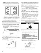
... burner flame adjustments. Complete Conversion 1. Re-engage anti-tip bracket if range is behind the oven burner air shutter. A C B D A. To Convert Oven Burner 1. The orifice spud is moved. Install the number "56" LP gas spud. LP oven orifice spud stamped with the bag containing literature. 6. Refer to complete this procedure. The outer cone is very important. Natural Gas Conversion WARNING Tip Over Hazard A child or adult can result in the gas supply line to the "closed " position C. Turn manual shutoff valve to the open...
... burner flame adjustments. Complete Conversion 1. Re-engage anti-tip bracket if range is behind the oven burner air shutter. A C B D A. To Convert Oven Burner 1. The orifice spud is moved. Install the number "56" LP gas spud. LP oven orifice spud stamped with the bag containing literature. 6. Refer to complete this procedure. The outer cone is very important. Natural Gas Conversion WARNING Tip Over Hazard A child or adult can result in the gas supply line to the "closed " position C. Turn manual shutoff valve to the open...
Installation Instructions
Page 15
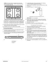
...A B A. Install the Natural gas orifice spuds using a flat-blade screwdriver. Spud B. The gas pressure regulator is stamped "110 (Red/Brass)." 3. Burner 2. Locate the Natural gas orifice spuds for top burners in the same position. Remove the LP gas orifice spuds using a 7 mm combination wrench. 4. To convert to Natural gas A B 180º C A. Reinstall the cap. A B A. Gas pressure regulator IMPORTANT: Do not remove the gas pressure regulator. Adjustment screw 4. To Convert Gas Pressure Regulator 1. A To Convert Surface Burners 1. A. A. NOTE: Do not remove the...
...A B A. Install the Natural gas orifice spuds using a flat-blade screwdriver. Spud B. The gas pressure regulator is stamped "110 (Red/Brass)." 3. Burner 2. Locate the Natural gas orifice spuds for top burners in the same position. Remove the LP gas orifice spuds using a 7 mm combination wrench. 4. To convert to Natural gas A B 180º C A. Reinstall the cap. A B A. Gas pressure regulator IMPORTANT: Do not remove the gas pressure regulator. Adjustment screw 4. To Convert Gas Pressure Regulator 1. A To Convert Surface Burners 1. A. A. NOTE: Do not remove the...
Installation Instructions
Page 16
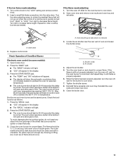
...burner flame adjustments. Locate Natural gas orifice spud stamped "47" in the gas supply line to the "Electronic Ignition System" section for each cooktop burner. Power burner - A B C A. Natural gas oven orifice spud stamped with flame spreader and set aside. 2. Refer to the "Make Gas Connection" section for proper cooktop and oven burner flames is not as distinct as the inner cone. Close the broiler door and press the CANCEL/OFF pad. 5. Standard burner - Simmer burner - Remove screw from the oven burner. Air shutter C. W10620413E ©2015. NOTE: The range cooktop...
...burner flame adjustments. Locate Natural gas orifice spud stamped "47" in the gas supply line to the "Electronic Ignition System" section for each cooktop burner. Power burner - A B C A. Natural gas oven orifice spud stamped with flame spreader and set aside. 2. Refer to the "Make Gas Connection" section for proper cooktop and oven burner flames is not as distinct as the inner cone. Close the broiler door and press the CANCEL/OFF pad. 5. Standard burner - Simmer burner - Remove screw from the oven burner. Air shutter C. W10620413E ©2015. NOTE: The range cooktop...


