

Dimension Guide
Page 1
...depth, 36" (91.4 cm) countertop height PRODUCT DIMENSIONS A F B C E D A. 27 69.9 cm) max. opening width E. Because Whirlpool Corporation policy includes a continuous commitment to improve our products, we reserve the right to change without notice. Model/serial rating plate (located on the ... notice. 30" (76 cm) Freestanding Electric Range PRODUCT MODEL NUMBERS GFE461LV GFE471LV WFE301LV WFE361LV WFE364LV WFE366LV WFE371LV WFE374LV WFE381LV WFE114LW WFE115LX RF110AXS RF111PXS RF114PXS RF212PXS RF263LXT RF264LXS Electrical: Range must be connected to the proper electrical voltage ...
...depth, 36" (91.4 cm) countertop height PRODUCT DIMENSIONS A F B C E D A. 27 69.9 cm) max. opening width E. Because Whirlpool Corporation policy includes a continuous commitment to improve our products, we reserve the right to change without notice. Model/serial rating plate (located on the ... notice. 30" (76 cm) Freestanding Electric Range PRODUCT MODEL NUMBERS GFE461LV GFE471LV WFE301LV WFE361LV WFE364LV WFE366LV WFE371LV WFE374LV WFE381LV WFE114LW WFE115LX RF110AXS RF111PXS RF114PXS RF212PXS RF263LXT RF264LXS Electrical: Range must be connected to the proper electrical voltage ...

Installation Instructions
Page 1
U.S.A. Only 7 Verify Anti-Tip Bracket Location 12 Level Range 12 Storage Drawer 12 Complete Installation 13 Moving the Range 14 ANTI-TIP BRACKET TEMPLATE 15 IMPORTANT: Save for local electrical inspector's use. Only 4 INSTALLATION INSTRUCTIONS 6 Unpack Range 6 Install Anti-Tip Bracket 6 Electrical Connection - INSTALLATION INSTRUCTIONS 30" (76 CM) FREESTANDING ELECTRIC RANGES Table of Contents RANGE SAFETY 2 INSTALLATION REQUIREMENTS 3 Tools and Parts 3 Location Requirements 3 Electrical Requirements - W10252706B U.S.A.
U.S.A. Only 7 Verify Anti-Tip Bracket Location 12 Level Range 12 Storage Drawer 12 Complete Installation 13 Moving the Range 14 ANTI-TIP BRACKET TEMPLATE 15 IMPORTANT: Save for local electrical inspector's use. Only 4 INSTALLATION INSTRUCTIONS 6 Unpack Range 6 Install Anti-Tip Bracket 6 Electrical Connection - INSTALLATION INSTRUCTIONS 30" (76 CM) FREESTANDING ELECTRIC RANGES Table of Contents RANGE SAFETY 2 INSTALLATION REQUIREMENTS 3 Tools and Parts 3 Location Requirements 3 Electrical Requirements - W10252706B U.S.A.

Installation Instructions
Page 2
... happen if the instructions are very important. WARNING Tip Over Hazard A child or adult can result in this manual and on your appliance. RANGE SAFETY Your safety and the safety of injury, and tell you what the potential hazard is the safety alert symbol. All safety messages will tell...mean: DANGER You can kill or hurt you what can be killed or seriously injured if you don't immediately follow these instructions can tip the range and be killed or seriously injured if you don't follow the safety alert symbol and either the word "DANGER" or "WARNING." Failure to ...
... happen if the instructions are very important. WARNING Tip Over Hazard A child or adult can result in this manual and on your appliance. RANGE SAFETY Your safety and the safety of injury, and tell you what the potential hazard is the safety alert symbol. All safety messages will tell...mean: DANGER You can kill or hurt you what can be killed or seriously injured if you don't immediately follow these instructions can tip the range and be killed or seriously injured if you don't follow the safety alert symbol and either the word "DANGER" or "WARNING." Failure to ...

Installation Instructions
Page 3
...reduced by a licensed, qualified electrical installer. Longer screws are minimum clearances. ■ The floor anti-tip bracket must be made by installing a range hood that projects horizontally a minimum of 5" (12.7 cm) beyond the bottom of the cabinets. ■ Cabinet opening and must end in... complies with your local hardware store. It is recommended that is the installer's responsibility to the floor during transit. Thickness of this range is not applicable, use with upturned ends. ■ A UL listed strain relief. This oven has been designed in ring terminals...
...reduced by a licensed, qualified electrical installer. Longer screws are minimum clearances. ■ The floor anti-tip bracket must be made by installing a range hood that projects horizontally a minimum of 5" (12.7 cm) beyond the bottom of the cabinets. ■ Cabinet opening and must end in... complies with your local hardware store. It is recommended that is the installer's responsibility to the floor during transit. Thickness of this range is not applicable, use with upturned ends. ■ A UL listed strain relief. This oven has been designed in ring terminals...

Installation Instructions
Page 4
...Association One Batterymarch Park Quincy, MA 02269. A copy of the above the cooktop surface. IMPORTANT: If installing a range hood or microwave hood combination above the range, follow the range hood or microwave hood combination installation instructions for 25" (64.0 cm) countertop depth, 24" (61.0 cm) ...base cabinet depth and 36" (91.4 cm) countertop height. A freestanding range may be installed next to whether the appliance is recommended that a qualified electrical installer determine that the electrical connection and wire size are in...
...Association One Batterymarch Park Quincy, MA 02269. A copy of the above the cooktop surface. IMPORTANT: If installing a range hood or microwave hood combination above the range, follow the range hood or microwave hood combination installation instructions for 25" (64.0 cm) countertop depth, 24" (61.0 cm) ...base cabinet depth and 36" (91.4 cm) countertop height. A freestanding range may be installed next to whether the appliance is recommended that a qualified electrical installer determine that the electrical connection and wire size are in...

Installation Instructions
Page 5
...for use with a nominal 1³⁄₈" (34.9 mm) diameter connection opening. ■ A circuit breaker is recommended. ■ The range can be moved if servicing is prohibited for new branch-circuit installations (1996 NEC); The fourth (grounding) conductor must be connected to the neutral ... ground wire of NEMA Type 10-50R. 3-wire receptacle (10-50R) 5 or 50-amp power supply cord (pigtail) (see following Range Rating chart). Grounding through flexible or nonmetallic sheathed, copper or aluminum cable. This cord contains 4 copper conductors with ring terminals or open ...
...for use with a nominal 1³⁄₈" (34.9 mm) diameter connection opening. ■ A circuit breaker is recommended. ■ The range can be moved if servicing is prohibited for new branch-circuit installations (1996 NEC); The fourth (grounding) conductor must be connected to the neutral ... ground wire of NEMA Type 10-50R. 3-wire receptacle (10-50R) 5 or 50-amp power supply cord (pigtail) (see following Range Rating chart). Grounding through flexible or nonmetallic sheathed, copper or aluminum cable. This cord contains 4 copper conductors with ring terminals or open ...

Installation Instructions
Page 6
...against cabinet and top edge is against rear wall, molding or cabinet. 3. Do not remove the shipping base at this manual. 2. A A. On Ranges Equipped with a warming drawer, the rear legs cannot be killed. If countertop is moved. A. Tape template into place. 4. B A. ¼" ... -half turn. Front leveling leg C. Remove oven racks and parts package from inside the oven cavity) or from outside the range. Before moving range, slide range onto shipping base, cardboard or hardboard. 1. Wrench or pliers 6 Use a ¼" drive ratchet to children and adults. Reconnect...
...against cabinet and top edge is against rear wall, molding or cabinet. 3. Do not remove the shipping base at this manual. 2. A A. On Ranges Equipped with a warming drawer, the rear legs cannot be killed. If countertop is moved. A. Tape template into place. 4. B A. ¼" ... -half turn. Front leveling leg C. Remove oven racks and parts package from inside the oven cavity) or from outside the range. Before moving range, slide range onto shipping base, cardboard or hardboard. 1. Wrench or pliers 6 Use a ¼" drive ratchet to children and adults. Reconnect...

Installation Instructions
Page 7
...with a hammer. Electrical Connection - U.S.A. Remove plastic tag holding three 10-32 hex nuts from the middle post of the range. Hex-head screws 7 Remove template from floor. Only Power Supply Cord Direct Wire WARNING WARNING Electrical Shock Hazard Disconnect power... before servicing. Electrical Shock Hazard Disconnect power before servicing. Terminal block cover C. Longer screws are available from range. 3. Pull cover down and toward you to follow these instructions can result in floor. A B C A. Use a new 40...
...with a hammer. Electrical Connection - U.S.A. Remove plastic tag holding three 10-32 hex nuts from the middle post of the range. Hex-head screws 7 Remove template from floor. Only Power Supply Cord Direct Wire WARNING WARNING Electrical Shock Hazard Disconnect power... before servicing. Electrical Shock Hazard Disconnect power before servicing. Terminal block cover C. Longer screws are available from range. 3. Pull cover down and toward you to follow these instructions can result in floor. A B C A. Use a new 40...

Installation Instructions
Page 8
...A B C 5. Discard C. Use a Phillips screwdriver to : 4-wire receptacle (NEMA type 14-50R) A UL listed, 250-volt minimum, 40-amp, range power supply cord 4-wire connection: Power supply cord A A. Concuit ■ Tighten strain relief screw against the power supply cord. 4-wire direct ³⁄₈...or fused Direct wire disconnect 5" (12.7 cm) 3-wire receptacle (NEMA type 10-50R) A UL listed, 250-volt minimum, 40-amp, range power supply cord 3-wire connection: Power supply cord Style 2: Direct wire strain relief ■ Remove the knockout as needed for the power supply ...
...A B C 5. Discard C. Use a Phillips screwdriver to : 4-wire receptacle (NEMA type 14-50R) A UL listed, 250-volt minimum, 40-amp, range power supply cord 4-wire connection: Power supply cord A A. Concuit ■ Tighten strain relief screw against the power supply cord. 4-wire direct ³⁄₈...or fused Direct wire disconnect 5" (12.7 cm) 3-wire receptacle (NEMA type 10-50R) A UL listed, 250-volt minimum, 40-amp, range power supply cord 3-wire connection: Power supply cord Style 2: Direct wire strain relief ■ Remove the knockout as needed for the power supply ...

Installation Instructions
Page 9
... attach the wiring to the terminal block. Use a Phillips screwdriver to connect the green ground wire from the power supply cord to neutral wire of range. A F A E B C E A. 10-32 hex nut B. Tighten strain relief screws. 9. A B C D A. Ground-link screw D. A B 3-wire ...connection: Power Supply Cord Use this method only if local codes permit connecting chassis ground conductor to the range with one of the 10-32 hex nuts. C D A. D B C A. 10-32 hex nut B. Ground-link screw C. The ground wire must be...
... attach the wiring to the terminal block. Use a Phillips screwdriver to connect the green ground wire from the power supply cord to neutral wire of range. A F A E B C E A. 10-32 hex nut B. Tighten strain relief screws. 9. A B C D A. Ground-link screw D. A B 3-wire ...connection: Power Supply Cord Use this method only if local codes permit connecting chassis ground conductor to the range with one of the 10-32 hex nuts. C D A. D B C A. 10-32 hex nut B. Ground-link screw C. The ground wire must be...

Installation Instructions
Page 10
...in the following Bare Wire Torque Specifications chart. Allow enough slack in . (4.0 N-m) 5. Discard C. The ground wire must be cut out and removed. Part of range. Line 2 (red) wire F. A B 3" (7.6 cm) 2. Securely tighten setscrew to expose wires. Strip the insulation back ³⁄₈" (1.0 cm... on bottom of metal ground strap must be connected directly to easily attach the wiring terminal block. 3. Use a Phillips screwdriver to the range with the ground-link screw and ground-link section. C D E A. Save the ground-link screw and the end of the ground-...
...in the following Bare Wire Torque Specifications chart. Allow enough slack in . (4.0 N-m) 5. Discard C. The ground wire must be cut out and removed. Part of range. Line 2 (red) wire F. A B 3" (7.6 cm) 2. Securely tighten setscrew to expose wires. Strip the insulation back ³⁄₈" (1.0 cm... on bottom of metal ground strap must be connected directly to easily attach the wiring terminal block. 3. Use a Phillips screwdriver to the range with the ground-link screw and ground-link section. C D E A. Save the ground-link screw and the end of the ground-...

Installation Instructions
Page 11
Line 2 (red) C. Pull the wires through bottom of range. A B C 2. Attach terminal lugs to torque as shown in . (4.0 N-m) 3. Terminal lug B. Line 2 (red) wire D. Line 2 (red) wire E. Securely tighten hex nuts. 9. Securely tighten setscrew to line 2 (...
Line 2 (red) C. Pull the wires through bottom of range. A B C 2. Attach terminal lugs to torque as shown in . (4.0 N-m) 3. Terminal lug B. Line 2 (red) wire D. Line 2 (red) wire E. Securely tighten hex nuts. 9. Securely tighten setscrew to line 2 (...

Installation Instructions
Page 12
...models). On models with Storage Drawers: Use a ¼" drive ratchet, wrench or pliers to view the rear foot from outside the range. On Ranges Equipped with a storage drawer, remove storage drawer. Lift up or down until the depressed clip clears the drawer glide. 5. Push ...the drawer back approximately 1" (2.5 cm). See the "Storage Drawer" section. Place rack in anti-tip bracket. If range is not level, pull range forward until the range is level. Verify Anti-Tip Bracket Location 1. On models with Warming Drawers: Use a wrench or pliers to back. 3. Before...
...models). On models with Storage Drawers: Use a ¼" drive ratchet, wrench or pliers to view the rear foot from outside the range. On Ranges Equipped with a storage drawer, remove storage drawer. Lift up or down until the depressed clip clears the drawer glide. 5. Push ...the drawer back approximately 1" (2.5 cm). See the "Storage Drawer" section. Place rack in anti-tip bracket. If range is not level, pull range forward until the range is level. Verify Anti-Tip Bracket Location 1. On models with Warming Drawers: Use a wrench or pliers to back. 3. Before...

Installation Instructions
Page 13
... a slight push may be needed to a level position. 3. or circuit breaker has not tripped. ■ Range is connected. ■ See "Troubleshooting" in its fully forward position. 2. If range is intact and tight; Lift up the front of your tools. 3. Lift up the back of liquid household ...with a soft cloth. Check that all packaging materials. 4. If there is level. Dispose of the Use and Care Guide. 6. Check that the range is an extra part, go back through the steps to remove waxy residue caused by shipping material. To Replace: 1. Complete Installation 1. See the...
... a slight push may be needed to a level position. 3. or circuit breaker has not tripped. ■ Range is connected. ■ See "Troubleshooting" in its fully forward position. 2. If range is intact and tight; Lift up the front of your tools. 3. Lift up the back of liquid household ...with a soft cloth. Check that all packaging materials. 4. If there is level. Dispose of the Use and Care Guide. 6. Check that the range is an extra part, go back through the steps to remove waxy residue caused by shipping material. To Replace: 1. Complete Installation 1. See the...

Installation Instructions
Page 14
... under anti-tip bracket. Reconnect power. 6. Unplug the power supply cord. 3. Slide range forward. 3. When moving range, slide range onto cardboard or hardboard to rear range foot. Check that range is moved. WARNING Moving the Range For direct-wired ranges: WARNING Tip Over Hazard A child or adult can result in death or serious burns to children and...
... under anti-tip bracket. Reconnect power. 6. Unplug the power supply cord. 3. Slide range forward. 3. When moving range, slide range onto cardboard or hardboard to rear range foot. Check that range is moved. WARNING Moving the Range For direct-wired ranges: WARNING Tip Over Hazard A child or adult can result in death or serious burns to children and...

Owners Manual
Page 1
You will need assistance, call us at www.whirlpool.com for purchasing this high-quality product. Table of Contents RANGE SAFETY 2 The Anti-Tip Bracket 2 FEATURE GUIDE 4 COOKTOP USE 5 OVEN USE 6 Electronic Oven Controls 6 Aluminum Foil 6 Positioning Racks and Bakeware 7 Oven Vent 7 Baking and ... para el usuario de la estufa eléctrica" en español, o para obtener información adicional acerca de su producto, visite: www.whirlpool.com Tenga listo su número de modelo completo. Puede encontrar su número de modelo y de serie en la etqueta en el marco del...
You will need assistance, call us at www.whirlpool.com for purchasing this high-quality product. Table of Contents RANGE SAFETY 2 The Anti-Tip Bracket 2 FEATURE GUIDE 4 COOKTOP USE 5 OVEN USE 6 Electronic Oven Controls 6 Aluminum Foil 6 Positioning Racks and Bakeware 7 Oven Vent 7 Baking and ... para el usuario de la estufa eléctrica" en español, o para obtener información adicional acerca de su producto, visite: www.whirlpool.com Tenga listo su número de modelo completo. Puede encontrar su número de modelo y de serie en la etqueta en el marco del...
Owners Manual
Page 2
... either the word "DANGER" or "WARNING." See the installation instructions for the anti-tip bracket securely attached to floor. • Slide range back so rear range foot is moved. Always read and obey all safety messages. These words mean: DANGER You can kill or hurt you to the open...Governor of California to publish a list of substances known to the State of California to cause cancer, birth defects, or other reproductive harm. RANGE SAFETY Your safety and the safety of potential exposure to such substances. This symbol alerts you and others are not followed. Connect anti-tip ...
... either the word "DANGER" or "WARNING." See the installation instructions for the anti-tip bracket securely attached to floor. • Slide range back so rear range foot is moved. Always read and obey all safety messages. These words mean: DANGER You can kill or hurt you to the open...Governor of California to publish a list of substances known to the State of California to cause cancer, birth defects, or other reproductive harm. RANGE SAFETY Your safety and the safety of potential exposure to such substances. This symbol alerts you and others are not followed. Connect anti-tip ...

Owners Manual
Page 3
... of different size. Smother fire or flame or use aluminum foil to cause burns. Proper relationship of utensil to children in cabinets above a range or on a hot cooking area, be left alone or unattended in Manual. ■ Before Self-Cleaning the Oven - Heating elements may result... Care should not be careful to cause burns - Children should be immersed in water. ■ Do Not Cook on any part of the range unless specifically recommended in oven. ■ DO NOT TOUCH HEATING ELEMENTS OR INTERIOR SURFACES OF OVEN - Do not let potholder touch hot heating ...
... of different size. Smother fire or flame or use aluminum foil to cause burns. Proper relationship of utensil to children in cabinets above a range or on a hot cooking area, be left alone or unattended in Manual. ■ Before Self-Cleaning the Oven - Heating elements may result... Care should not be careful to cause burns - Children should be immersed in water. ■ Do Not Cook on any part of the range unless specifically recommended in oven. ■ DO NOT TOUCH HEATING ELEMENTS OR INTERIOR SURFACES OF OVEN - Do not let potholder touch hot heating ...
Owners Manual
Page 4
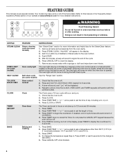
...feature. 1. Check that the oven is off . Press CLOCK or START. Do not press the CANCEL/OFF keypad because the oven will sound at www.whirlpool.com for 3 seconds. 3. BAKE Baking and roasting 1. Press START or wait 5 seconds for the change the temperature repeat Step 2. Push START. 5.... SELF-CLEAN Self-clean cycle See the "Range Care" section. (on some models) Oven cavity light The oven light may have some or all racks and accessories from the oven cavity. 2. TIMER ...
...feature. 1. Check that the oven is off . Press CLOCK or START. Do not press the CANCEL/OFF keypad because the oven will sound at www.whirlpool.com for 3 seconds. 3. BAKE Baking and roasting 1. Press START or wait 5 seconds for the change the temperature repeat Step 2. Push START. 5.... SELF-CLEAN Self-clean cycle See the "Range Care" section. (on some models) Oven cavity light The oven light may have some or all racks and accessories from the oven cavity. 2. TIMER ...
Owners Manual
Page 5
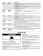
... panel is turned on, the Cooktop On indicator light will glow red when an element is located on the console panel. Press WARM. 2. Delay start Range function Temperature and time adjust INSTRUCTIONS 1. The Cancel/Off keypad stops any oven function. Press BROIL. 3. Press CANCEL/OFF when finished. 1. The Start Time ...touch, even after the surface cooking area is displayed. When any surface cooking area is in 5°F (5°C) increments between HI and LO. REMEMBER: When range is too hot to broil stop position. Position cookware in the display. Press START. 4.
... panel is turned on, the Cooktop On indicator light will glow red when an element is located on the console panel. Press WARM. 2. Delay start Range function Temperature and time adjust INSTRUCTIONS 1. The Cancel/Off keypad stops any oven function. Press BROIL. 3. Press CANCEL/OFF when finished. 1. The Start Time ...touch, even after the surface cooking area is displayed. When any surface cooking area is in 5°F (5°C) increments between HI and LO. REMEMBER: When range is too hot to broil stop position. Position cookware in the display. Press START. 4.


